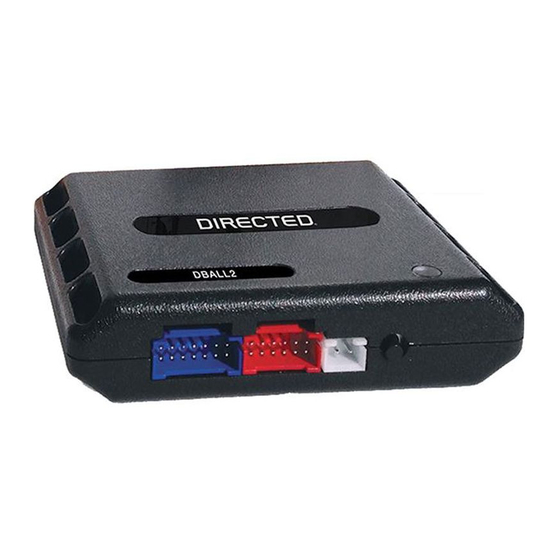
Directed XpressKit DBALL Manuel - Page 3
Parcourez en ligne ou téléchargez le pdf Manuel pour {nom_de_la_catégorie} Directed XpressKit DBALL. Directed XpressKit DBALL 14 pages. Ford5 remote start ready (rsr) installation
Également pour Directed XpressKit DBALL : Manuel d'installation (16 pages), Manuel d'installation (16 pages), Manuel (19 pages)

Platform: DBALL/DBALL2
Firmware: FORD5 Range Extender Ready (RXT) Installation
Wiring Diagram
Important!
The Remote Start Safety Override Switch is a mandatory safety device, but is NOT supplied with the DBALL.
OBDII Diagnostic Connector
MS CAN High:
HS CAN High:
Gray/Orange, pin 3
White/Blue, pin 6
1
8
9
16
MS CAN Low:
HS CAN Low:
Violet/Orange, pin 11
White, pin 14
(-) Ground:
Black or Black/White, pin 4
With the exception of the OBDII Diagnostic connector, all adapters are displayed from the wire side (unless specified otherwise).
MS CAN High: Tan/Black: 3
MS CAN Low: Tan: 4
(+) 12V:
pin 16
HS CAN High: Orange/Green: 5
HS CAN Low: Orange/Brown: 6
(+) 12V: Red: 13
(-) Ground: Black: 14
RF
DBALL/
Prog. Button
DBALL2
LED
You can connect to either a XL202
RFTD OR a SmartStart module.
Refer to the SmartStart/XL202
Installation Notes for more information.
Rev.: 20160317
Page 3
© 2016 Directed. All rights reserved.
