Aleko AR2000 Manuel de l'utilisateur - Page 10
Parcourez en ligne ou téléchargez le pdf Manuel de l'utilisateur pour {nom_de_la_catégorie} Aleko AR2000. Aleko AR2000 16 pages.

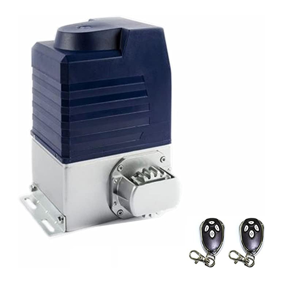
AR2000 SLIDING GATE OPERATOR
Schematic diagram
15. Output power supply: +12V (DC +12V), COM (CO),DET (Loop detector), I.R. (Infrared N.C)
COM
Out
GND
+12V
Infrared
Infrared with DC input
COM
Out
GND
+12V
Loop detector
Loop detector with DC input
16. Beeper: DC12V
17. Learn button: AN
18. Dip-switch
19. Antenna: ANT
7. Control
Remote control: The remote control works in a single channel mode. It has four buttons.
See Fig.10 Remote control. The function of button 1, button 2 and button3 are the same.
With each press of the remote control button, which has been programmed, the gate will
close, stop, open or stop cycle. Button 4 is available to set pedestrian mode.
You can program/learn button 1, button 2, button 3 individually. You also can program/learn
two buttons or three buttons together, but you need repeat the program/learn process if you
want to use more than one button.
G
NO
com
K
NO
com
COM
I.R
Terminal
COM
X8, No.15
+12V
Control board
COM
DET
Terminal
COM
X8, No.15
+12V
Control board
Schematic diagram
10
Not used
T
Open
G
Signal
K
Com
GND
Control board
Button switch
keypad
terminal X7
Wiring diagram
COM
Out
AC24V
Infrared
Infrared with AC input
COM
Out
AC24V
Loop detector
Loop detector with AC input
COM
Terminal
X8, No.15
I.R
Terminal
AC24V
X5,No.11
Control board
COM
Terminal
X8, No.15
DET
AC24V Terminal
X5,No.11
Control board
