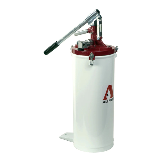
Alemite 6713-4 Manuel d'entretien - Page 2
Parcourez en ligne ou téléchargez le pdf Manuel d'entretien pour {nom_de_la_catégorie} Alemite 6713-4. Alemite 6713-4 10 pages. High-pressure bucket pump

SER 6713-4
Model Assembly
Refer to Figure 2-A for the assembly of the
components that are shipped loose.
Filling
The pump's container can be filled from a transfer
pump or manually.
NOTE: The three steps that follow consider
the pump without a follower plate.
Transfer Pump Loading
NOTE: Refer to Figure 2-A for component
identification on the following procedures.
1. Slide the fill-hole cover away from the pump.
2. Insert the hose from the transfer pump into the
opening.
• Make sure the hose reaches the bottom of Container
Assembly (7) or the surface of the product.
IMPORTANT: Keep the end of the hose (or
wand) just underneath the surface of the
grease. This prevents air from mixing with
the product during the fill process.
3. Fill the Container within 2-inches (5 cm) from the top.
Manual Loading (Paddle)
4. Loosen Knobs (3) from the bolts on Container
Assembly (7).
• Swing the bolts away from Cover Assembly (9).
CAUTION
Point the bottom of the pump tube upward. Pre-
vent contamination from foreign material. Damage
to components can occur.
5. Remove the cover and pump assembly from the
Container Assembly.
6. Fill the Container within 2-inches (5 cm) from the top.
• Do not allow air to be entrapped during the filling
process.
7. Place the optional follower plate onto the top of the
product.
• With a wobbling motion, eliminate any air that may
be trapped underneath the follower. Force the
product through the hole in the center of the plate.
Revision (2-02)
8. Position the cover and pump tube assembly into the
follower plate and fit the Cover onto the Container.
9. Secure the Cover to the Container with the Knobs.
Operation
WARNING
Do not exceed the lowest pressure rating of
any component in the system.
Ensure all components are in operable condition.
Replace any suspect parts prior to operation.
Personal injury can occur.
Priming the Pump
NOTE: Refer to Figure 2-B for component
identification on the following procedures.
1. Turn Bleed Valve Screw (26) counterclockwise to open.
2. Make sure Pressure-Relief Valve Screw (29) is closed.
3. Cycle the Lever until product causes the cycling of the
Lever to stiffen.
If the pump assembly does not prime, refer to the
Troubleshooting Chart for details.
4. Close the Bleed Valve Screw until it seats.
Dispensing
5. Wipe the end of the coupler and the fitting to be
lubricated with a clean cloth.
6. Attach the coupler to the lubrication fitting.
7. Operate the lever until the proper amount of lubricant is
dispensed.
NOTE: Certain applications can create exces-
sive back-pressure at the fitting that inhibits
the removal of the coupler. Should this occur:
8. Turn Pressure-Relief Valve Screw (29)
counterclockwise to open.
• This allows the product within the delivery hose to
return to the Container.
9. Remove the coupler from the fitting and close the
Pressure-Relief Valve Screw.
NOTE: Should the Lever be stopped in the
upward position:
10. Turn Bleed Valve Screw (26) counterclockwise to open.
• This allows the Lever to be pushed downward without
product discharge.
2
High-Pressure Bucket Pump
Alemite Corporation
