Alemite 8301 Manuel d'instructions de service - Page 2
Parcourez en ligne ou téléchargez le pdf Manuel d'instructions de service pour {nom_de_la_catégorie} Alemite 8301. Alemite 8301 11 pages. Air-operated double diaphragm pump
Également pour Alemite 8301 : Manuel d'entretien et d'utilisation (10 pages)
SER 8301
4. Never point the dispensing device at anyone.
Accidental discharge can cause serious injury.
5. Shut off the air pressure and relieve all material
pressures before attempting to service any part.
6. Check for leaks before starting any pumping
operation. If any leaks or other abnormalities are
found, do not operate the pump.
7. Wear safety glasses at all times when operating
the pump.
8. Wear a face shield and proper body protection
when working with hazardous chemicals.
9. When pumping Class 1 Hazardous (flammable)
liquids, use pump outdoors or in an OSHA approved
location.
10. When pump is used with flammable or Class 1 ma-
terials, the following procedures must be strictly applied:
A. A special "static hose" must be used which has
a provision for conducting static electrical charges.
B. Hose must be properly grounded with a
grounding conductor.
C. Pump and entire system must be properly
grounded, in accordance with local and national
codes.
WARNING: Unless proper grounding is followed,
static discharge can cause a fire or an explosion.
INSTALLATION
There are many possible configurations in which the
pump can be connected. Specific installations will
depend on the fluid being pumped and the application.
NOTE: For best results, it is recommended that an
air filter/moisture separator (such as the Alemite
5604-2) and an air-pressure regulator (such as the
Alemite 7604-B) be used in the air line.
WARNING: The pump must be grounded to prevent
any sparks when pumping flammable or volatile liquids.
NOTE: The inlet and outlet manifolds are reversible
to facilitate connecting the hoses from either
direction.
1. Connect a suction hose from the supply container
to the pump fluid inlet.
2. Connect a discharge hose to the pump fluid outlet.
page 2
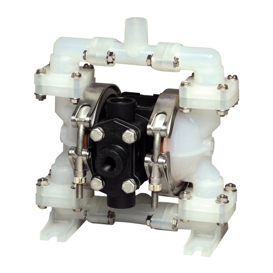
8-7/8
Fluid
Outlet
1/2" NPT
8-7/32
Fluid
Inlet
1/2" NPT
2-3/32
2-17/32
5-29/32
Air
Exhaust
3/8" NPT
4-29/32
3-29/32—4-15/16
7-3/32
Figure 2: Dimensions & Locations
11-29/32
4-7/8
Air
Supply
1/4" NPT
7-5/16
page revised 6-03