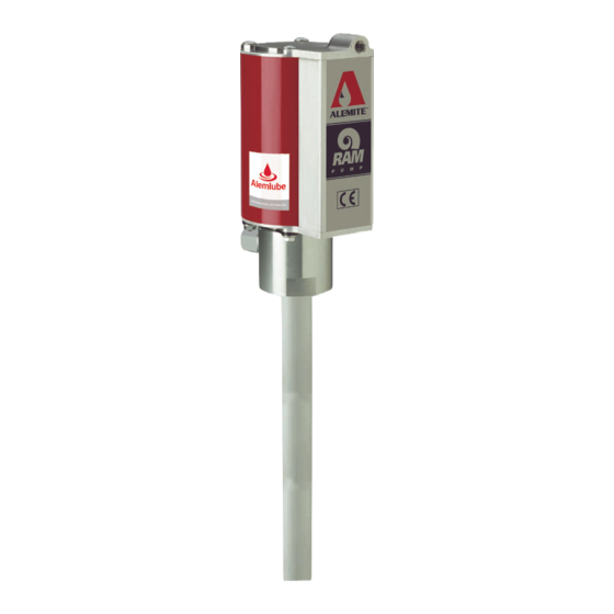
Alemite 9911-1 Manuel d'entretien - Page 9
Parcourez en ligne ou téléchargez le pdf Manuel d'entretien pour {nom_de_la_catégorie} Alemite 9911-1. Alemite 9911-1 12 pages. High-pressure stripped pump
Également pour Alemite 9911-1 : Manuel d'entretien du propriétaire (16 pages), Manuel d'entretien (12 pages)

High-Pressure Grease Pump
Figure 4 Pump Tube Assembly 338086-A1 and -C1 - Section View
Alemite, LLC
Refer to Figures 2-A and 2-B Parts List
for Parts Identification
Pump Tube Assembly
1. Install and seat Seal (12) [heel end
first] into the bottom of the Body.
2. Install and seat Lantern Ring (13)
[small diameter end first] into the
Body.
3. Install and seat Seal (14) [heel end
first] into the Body.
4. Install and seat Bearing (15) [small
diameter end first] into the Body.
5. Install and seat Gasket (16) into the
Body.
Steps for Model 9979 Only
6. Screw Rod (9) into Extension (23)
until the Pin holes align.
• Secure the Extension to the Rod
with Roll Pin (24).
7. Install Ball (27), Spring (26), and
Spring Guide (25) [pointed end first]
into Piston (28).
8. Screw the Piston assembly onto the
Extension until the Pin holes align.
• Secure the Piston to the Extension
with Roll Pin (24).
9. Screw the Piston assembly onto the
Rod until the Pin holes align.
• Secure the Piston to the Rod with
Roll Pin (24).
10. Screw Primer Rod (38) into the Piston
assembly until the Pin holes align.
• Secure the Piston assembly to the
Primer Rod with Roll Pin (29).
11. Install and seat Bearing (30), Seal
(31) [heel end first], and additional
Bearing (30) into the externally
threaded end of Lower Tube (33).
12. Install and seat Gasket (32) into the
internally threaded end of Lower
Tube (22).
9
SER 9930
Step for Model 9979 Only
Step for Model 9930 Only
Revision (8-10)
