Nikon WR-R10 Manuel de l'utilisateur - Page 5
Parcourez en ligne ou téléchargez le pdf Manuel de l'utilisateur pour {nom_de_la_catégorie} Nikon WR-R10. Nikon WR-R10 6 pages. Wireless remote controller/wr adapter
Également pour Nikon WR-R10 : Manuel de l'utilisateur (2 pages), Manuel de l'utilisateur (2 pages), Manuel de démarrage rapide (6 pages), Manuel (6 pages)

SURRiied Accessories
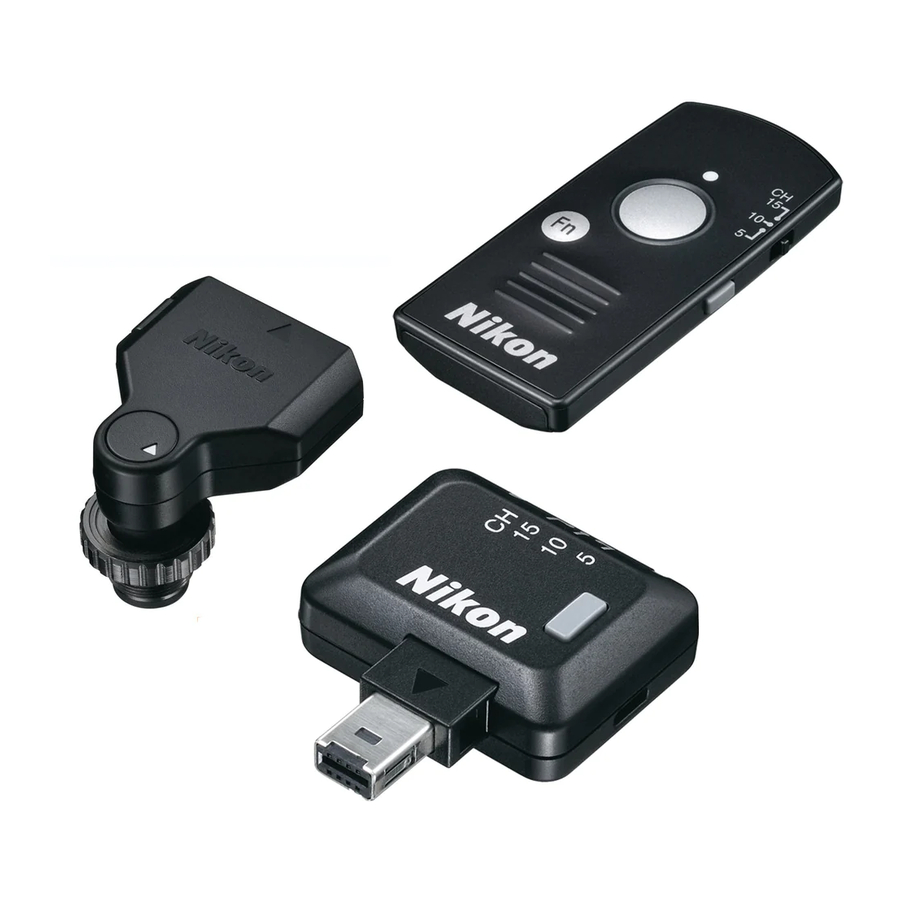
The product is sold in the sets below. This manual as-
sumes you have a WR-R1 0, WR-T1 0, and WR-A 10.
O
Case
0
Warranty
WR-R
1
0
0
Strap for WR-R1 0
0
Strap for WR-T1 0
~::A~h
o
CR2032 3
v
lithium battery'
0
User's Manual (this manual)
WR-R 1 0
0
Case
0
Warranty
0
Strap for WR-R1 0
0
User's Manual (this manual)
0
Strap for WR-T1 0
0
Warranty
WR-T10
O
CR2032 3 V lithium battery*
O
User's Manual (this manual)
WR-A10
0
User's Manual (this manual)
*Remove insulating sheet from WR-T10 before first use.
Parts of the Controller (Figure 1 ),
_ _ _ _ _ _
G) Red LED
®Channel selector
@Green LED
@
Pairing button
®
Strap eyelet
®Shutter-release button
0
Fn button
@
Strap eyelet
®
Red LED
@)Channel selector
@
Pairing button
~Hi~Jg
@
Release button
@Mounting mark
· · · · B
The WR-Rl 0 Strap
. Attach the WR-R1 0 to the camera strap as shown in
Figure 2 to prevent the WR-R1 0 being lost or dropped.
·····
· · · · B
Replacing CR2032 3 V Lithium Batteries {Figure 3)
·····
Replace the battery when the LED for the WR-T1 0 starts
· · · · to dim. Insert a fingernail behind the battery-chamber
latch and open the battery chamber (G)). Ensure that
· · · · · the battery is inserted in the correct orientation
(@)).
Using the WR-R1 0 (Transceiver),
_ _ _ _ _ _
_
Cameras with accessory terminals (Figure 4-a): Connect the
WR-R1 0 as shown by the marks on the camera (_.)
and WR-R1 0
('~).
Digital cameras with ten-pin remote terminals (Figure 4-b):
Attach the WR-A 10 WR adapter (G)) as shown by
the marks on the adapter (_.) and WR-R1 0
(T)
and
connect the assembly to the ten-pin remote terminal
(@),keeping the mounting mark on the WR-A 10 (G))
aligned with thee mark on the terminal. Tighten the
WR-A 1 0 locking screw
(@)).
Film cameras with ten-pin remote terminals (Figure 5): If the
terminal is on the front of the camera, remove the lens
or camera body cap (G)). Attach the WR-A 10, keep-
ing the mounting mark (G)) aligned with the mark on
the terminal (@). After tightening the WR-A 10 lock-
ing screw(@)), rotate the WR-A 10 (@)and attach the
WR-R1
0
(@)as shown by the marks on the adapter
(_.)and WR-R1 0 (T).
Note: Be sure the connectors are in the correct orienta-
tion; do not use force or insert the connectors at an an-
gle. Note that the WR-R1 0 can not be used with certain
accessories. Using force or inserting connectors at an
angle could damage the camera or accessory.
To remove the WR-R10, reverse the above steps. To re-
move the WR-A 10, press the release button (Figure
1-@) while sliding the adapter from the WR-R1 0.
B
The Fn Button
When a WR-R1 0 is mounted on the cameras below, the
· Fn button on the WR-T1 0 performs the function current-
ly assigned to the camera Fn button. See the camera
manual for details.
· 04
·
D800/800E
Using the WR-T1 0 (Transmitter),
_ _ _ _ _ _
_
The shutter-release button on the WR-T1 0 performs
the same functions as the camera shutter-release
button whether pressed halfway or all the way down.
See the camera manual for details.
B
Channel Selection and Pairing
If the camera fails to respond to the shutter-release but-
ton on the WR-T1 0, re-establish the link between the
WR-T1 0 and the receiver by matching channels and
pairing the devices as described below.
1
Set the units to the same channel.
Set the channel selectors on
both units to the same channel
(5, 1 0, or 15). Devices on differ-
ent channels can not be paired,
while paired devices can only
be used together when both
are set to the same channel.
2
Pair the devices.
After turning the camera on,
place the two devices close
together and press the pairing
buttons on both units simultane-
ously. Keep the buttons pressed
until the red and green LEOs on the WR-R1 0 flash on
and off in sequence, indicating that pairing is complete.
To erase pairing data, turn the camera on and keep the
WR-R1 0 pairing button pressed for about 3 seconds until
the green LED flashes rapidly, and then quickly press the
pairing button twice before the green LED stops flash-
ing. The green and red LEOs will both flash twice simul-
taneously to show that all pairing data has been erased.
