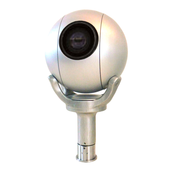
Camera Corps Q-Ball Manuel d'utilisation - Page 5
Parcourez en ligne ou téléchargez le pdf Manuel d'utilisation pour {nom_de_la_catégorie} Camera Corps Q-Ball. Camera Corps Q-Ball 9 pages. Camera corps q-ball robotic color camera

Q-Ball – Operation Manual
Component Video Output
Version 6 Interfaces have an additional 9 way 'D' Male connector on the side of the box.
This provides a component video output when HD modes are selected, or an S-Video and output when
SD modes are selected.
Version 6 also includes a Composite monitoring output (low quality) on pin 4 of the connector.
Serial Data input
An alternative to the audio data input is available in the form of serial RS232 or RS422 data. This is
connected to the 9 way 'D' male as shown in the connection listing below.
Links inside the interface box must be changed to allow serial rather than the audio data input to be used.
Link 2 is connected to allow serial data inputs. (In the unconnected mode it is left on just one of the link
pins). Link 3 is moved to set either RS232 or RS422 style data inputs. Both of these links are labelled
showing their function on the PCB. Note that serial baud rate is not selectable and must be 9600.
See Appendix 'C' for lid removal instructions.
Video Output 9 way 'D' Connections – Female connector on cable
HD Modes
1.
Y output
2.
Pr output
3.
Pb output
4.
NC
5.
RS422 +ve
or RS232 input
6.
0v
7.
0v
8.
0v
RS422 –ve
9.
SD Modes
1.
Y output
2.
Unused
3.
C output
4.
Composite Video (PAL or NTSC depending on mode selected). (V5 and later only).
5.
RS422 +ve
or RS232 input
6.
0v
7.
0v
8.
0v
RS422 –ve
9.
V6.3
(Luminance)
(Chrominance)
Page 4 of 8
2/2/2013
