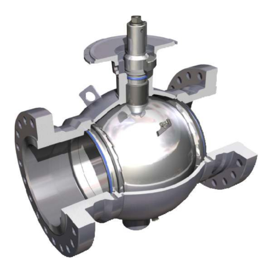
Cameron TYPE 31 Manuel d'installation, d'utilisation et d'entretien - Page 6
Parcourez en ligne ou téléchargez le pdf Manuel d'installation, d'utilisation et d'entretien pour {nom_de_la_catégorie} Cameron TYPE 31. Cameron TYPE 31 20 pages. Fully welded body ball valve

Hydrostatic Testing
When CAMERON T31 Fully Welded Body Ball Valves
are installed in a piping system that requires hydrostatic
testing of the adjoining pipe, follow these procedures
to minimize any damage that could occur to the
sealing surfaces and seat seals inside the valve.
1. Valve should be in the fully open position when
the injection of test fluid begins. This will allow
any pipeline debris to be flushed through the
valve bore and out of the piping.
2. Once the piping system has been purged of
debris and the system has been filled completely
with the test fluid, the ball valve should be placed
in the partially open position (approximately 10°
from the fully open position). This allows test
fluid into the body cavity of the valve.
3. The valve is now ready to be pressure tested.
4. Upon completion of hydrostatic testing, the valve
should be returned to the fully open position
before removing the test fluid from the piping
system. The test fluid in the body cavity can be
drained through the body drain port located on
the lower portion of the valve body.
5. Once the valve and piping system have been
pigged and customer product is injected into the
piping system, the valve should be moved to the
partially open position (approximately 10° from
the fully open position). Any remaining test fluid
trapped in the valve body cavity can then be
vented through the body bleed plug, located on
the lower portion of the valve body. If the valve
has been fitted with a stem extension, the vent
fitting will be located below the mounting flange
on top of the extension.
6. Opening the body bleed fitting will force trapped
test fluid out of the body cavity. Keep the bleed
plug open until all fluids have been exhausted
through the body bleed plug.
7. Close the valve body bleed fitting and return the
valve to the fully open position or the required
operating position.
8. The valve seat pockets should be filled with an
approved valve flush product to displace any
test fluid. Refer to Routine Seat Cleaning which
appears on page 7.
Mounting the Gear/Actuator
To mount a gear or power operator on a valve, use
the following guidelines. Note: The guidelines
given are for typical gear and actuator designs.
Specific instructions for each design should be
obtained from the gear / actuator manufacturer.
1. Make sure the valve is in the fully open or closed
position and position the actuator to match.
Installation, Operation and Maintenance Manual
E N G I N E E R E D V A L V E S
2. Depending on the valve stem and the actuator/
gear mounting kit, it is possible that the actuator
may be installed in multiple positions. If this is
the case, determine where the customer desires
the handwheel or actuator control panel and
install it accordingly. (A thin layer of antiseeze on
the valve stem is recommended.)
3. Once the operator is mounted, secure it with the
appropriate bolts. If the bolt holes do not line up,
slightly operate to the open or closed to match
the mounting flange. If you are unable to operate
the operator, performing steps 2 and 3 of Setting
Stops may need to be conducted.
4. It is now necessary to set the operator stops as
outlined in the following section.
Setting Stops
Gear Operator with Stops
1. Make sure that operating the valve to the fully
open and fully closed position will not disrupt
current operation of line.
2. Loosen the open and closed stop screw locknuts.
3. Turn stop screws counter-clockwise to increase
gear travel.
4. Operate the valve to the fully open position.
5. Utilize the stem stop viewports to verify valve
position. (Refer to Open and Closed Viewports
on page 6.)
6. Turn the open stop screw clockwise until it stops,
then tighten the locknut. If the stop screws will
not turn, repeat steps 3 and 4.
7. To set the closed stop, conduct steps 3 - 6,
operating the valve to the closed position and
utilize the closed stop.
STOP SCREW (CLOSED)
LOCKNUT
APPROXIMATE LOCATION OF BLANKING PLUGS (IF PRESENT)
Figure 5 - Typical Gear Box with Stops.
4
STOP SCREW (OPEN)
LOCKNUT
OPEN
INDICATOR CAP
(SHOWN OPEN)
IOM-CAM-BALL-T31
