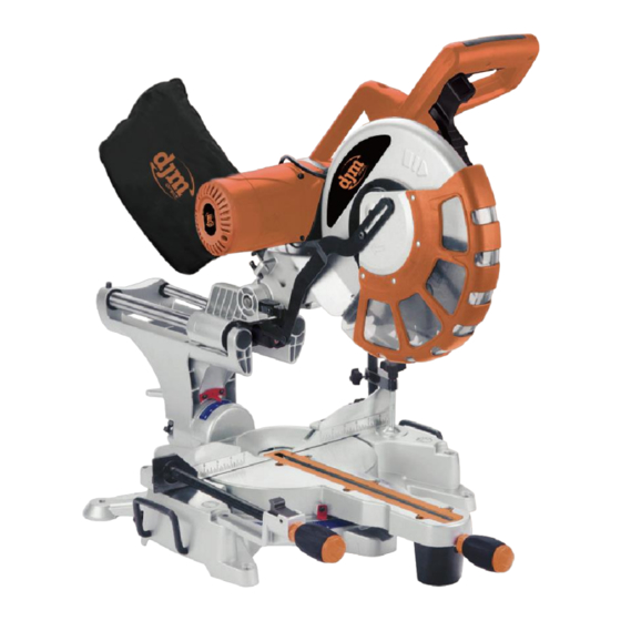
djm direct DJMSL12 Manuel d'utilisation - Page 8
Parcourez en ligne ou téléchargez le pdf Manuel d'utilisation pour {nom_de_la_catégorie} djm direct DJMSL12. djm direct DJMSL12 15 pages. 12 double bevel compound sliding mitre saw

– Reposition the blade guard (5) and secure this with the two screws
(26).
– Guide the retracting blade guard downward into its original
position.
Before any work on the machine itself, remove the mains plug from
outlet.
Transport Safety
The transport safety lock (24) enables easier handling of the machine
when transporting to various working locations.
Releasing the Machine (Working Position)
– Push the tool arm by the handle (1) down a little in order to relieve
the transport safetylock (24).
– Pull the transport safety lock (24) completely outward and turn 90°,
and loose.
– Guide the tool arm slowly upward.
Securing the Machine (Transport Position)
– Pull out the transport safety lock (24) then press lever (4) and at
the same time, swing the tool arm by handle (1) toward the saw
table (13)until it reaches the saw table. Pull out transport safety lock
(24) and turn 90° and push in to secure.
The tool arm is now securely locked for transport.
Mounting the Extension Bars
To extend the saw table additionally, extension bars are mounted
both to the left and right of the power tool.
– Loosen the extension bar lock (29) then pull out the extension bar
(15) to the desired length.
– Tighten the extension be lock (29) to secure the extension bar (15)
Extending the Fence
For bevel angles, the fence (8) must be extended.
– Loosen fence extension cap screw (30) using a hex key, and loosen
fence extension lock (31).
– Slide out the fence (8) to the desired position
– Tighten the both (30) & (31) again.
Setting the Trenching Facility
In its normally set position the trenching facility (19) permits the
blade to cut completely through the workpiece, but when set the
trenching facility (19) allows the blade to cut only part way through
the workpiece.
– With the tool in the working position, pull the trenching stop (32)
towards the front of the tool.
– Adjust the depth screw (33) to the desired length. Check height by
pulling down blade as if to cut workpiece.
– Tighten the depth lock (34) to lock the depth screw into position.
Clamping the Workpiece
To ensure optimum working safety, the workpiece must always be
firmly clamped.
Do not saw workpieces that are too small to clamp.
While clamping the workpiece, do not reach under the clamping
lever of either of the clamps with your fingers.
– Press the workpiece firmly against the fence (8).
– Insert the fast clamp (7) into one of the holes intended for this
purpose.
– Adapt the fast clamp to the workpiece by turning the threaded rod.
– Tighten the main screwin order to clamp the workpiece.
Adjusting the Cutting Angle
To ensure precise cuts, the basic adjustment of the machine must be
checked and adjusted as necessary after intensive use.
Always tighten the locking knob (10) & (18) firmly before sawing.
Otherwise the saw blade can become wedged in the work piece.
Adjusting Standard Mitre Angles or Any Angle
7
