Altronix AL1012X220 Series Manuel d'installation - Page 2
Parcourez en ligne ou téléchargez le pdf Manuel d'installation pour {nom_de_la_catégorie} Altronix AL1012X220 Series. Altronix AL1012X220 Series 4 pages.
Note: When servicing the unit, AC mains should be removed.
5. For Access Control applications batteries are optional. When batteries are not used, a loss of AC will result in the
loss of output voltage. When the use of stand-by batteries is desired, they must be lead acid or gel type.
6. Connect appropriate signaling notification devices to terminals marked [AC FAIL] and [BAT FAIL] (Fig. 1, pg. 5)
supervisory relay outputs.
Note: When used in fire alarm, burglar alarm or access control applications, "AC Fail" relay must be used to
provide a visual indication of AC power on.
USE 14 AWG or larger for all power connections.
Note: Take care to keep power-limited circuits separate from non power-limited wiring (220VAC, Battery).
Unit should be tested at least once a year for the proper operation as follows:
Output Voltage Test: Under normal load conditions the DC output voltage should be checked for proper voltage level.
Battery Test: Under normal load conditions check that the battery is fully charged, check specified voltage both at the
battery terminal and at the board terminals marked [– BAT +] to ensure that there is no break in the battery connection wires.
Note: Maximum charging current under discharges is 0.7A.
Note: Expected battery life is 5 years; however, it is recommended changing batteries in 4 years or less if needed.
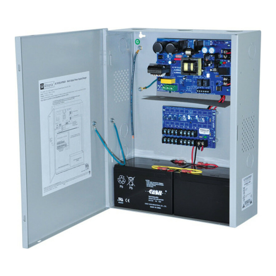
AL1012XB220 - Power Supply Board
Red (DC)
Green (AC)
ON
ON
ON
OFF
OFF
ON
OFF
OFF
PD4/PD4CB/PD8/PD8CB - Power Distribution Module
Green
Power Distribution Module Status
ON
Normal operating condition.
OFF
No Power Output.
AL1012XB220 - Power Supply Board
Terminal Legend Function/Description
Connect 220VAC (working range 198VAC - 256VAC), 50/60Hz to these terminals:
L, N
L to Hot, N to Neutral. Do not use the [G] terminal.
--- DC +
12VDC @ 10A continuous non power-limited output.
Indicates loss of AC power, e.g. connect to annuciator/alarm panel. Relay normally energized when
AC power is present. Contact rating 1A @ 30VDC. AC Fail condition will report approximately
AC FAIL
one (1) minute after the loss of AC. To delay report for 6 hours cut jumper J1 on the Power Supply
NC, C, NO
Board (AC trouble output delay option). If this mode is selected, the Power Supply Board must be
reset by removing all power to it for 30 seconds.
Indicates low battery condition, e.g. connect to alarm panel. Relay normally energized when DC
BAT FAIL
power is present. Contact rating 1A @ 30VDC. Low battery conditions will report approximately
NO, C, NC
10.5VDC. Battery presence detection will report approximately 1 minute after battery remains unde-
tected (missing or removed).
+ BAT ---
Stand-by battery connections. Maximum charge rate 0.7A.
PD4/PD4CB/PD8/PD8CB - Power Distribution Module
Terminal Legend
PD4/PD4CB
PD8/PD8CB
1P to 4P
1P to 8P
1N to 4N
1N to 8N
- 2 -
Wiring:
Maintenance:
LED Diagnostics:
Power Supply Status
Normal operating condition.
Loss of AC. Stand-by battery supplying power.
No DC output.
Loss of AC. Discharged or no stand-by battery. No DC output.
Terminal Identification:
Function/Description
Positive DC power outputs.
Negative DC power outputs.
AL1012X220 series