Altronix AL1012X220 Series Manuel d'installation - Page 3
Parcourez en ligne ou téléchargez le pdf Manuel d'installation pour {nom_de_la_catégorie} Altronix AL1012X220 Series. Altronix AL1012X220 Series 4 pages.
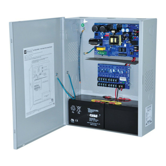
Fig. 1
CAUTION: De-energize unit prior to servicing. For continued protection
against risk of electric shock and fire hazard replace fuse with the same type
and rating 15A, 32V.
Door
Wire Strap
(from
Enclosure
to Door)
Fig. 2
F1
F2
F1
Used
1P, 2P, 3P, 4P = FUSED OUTPUTS
1N, 2N, 3N, 4N = COMMON OUTPUTS
on PTC
Models
1P
1N
2P
2N
C O M M O N
P O W E R
DC Output to devices
AL1012X220 series
BAT FAIL
5A 250V
NC C NO NC C NO
Battery and AC
220 power mains
Supervision Circuit
Use separate knockout
Power Distribution Module
1
2
DC Output to devices
Power Distribution Module(s):
F3
F4
PD4
POWER DISTRIBUTING UNIT
LED
3P
3N
4P
4N
O U T P U T S
From Power Supply
Board
(Factory Installed)
VR1
15
AC FAIL
Provide 0.25"
separation between
all other circuits
INPUT
12VDC Rechargeable Battery
(optional)
Fig. 3
1
P
Used
on PTC
Models
N
INPUT
Divider
1
2
3
4
5
6
7
F U S E D
P O W E R
O U T P U T S
C O M M O N
P O W E R
O U T P U T S
DC Output to devices
8
PD8
D1
LED
R1
INPUT
From Power Supply
Board
(Factory Installed)
- 3 -