Aion Electronics L5 Preamp Manuel - Page 12
Parcourez en ligne ou téléchargez le pdf Manuel pour {nom_de_la_catégorie} Aion Electronics L5 Preamp. Aion Electronics L5 Preamp 15 pages. Preamp, overdrive & limiter

Wiring Diagram
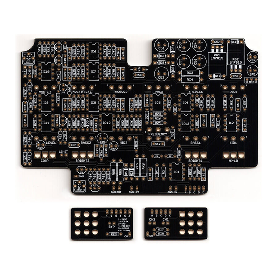
Shielded wire: Additional ground pads are provided next to the In, Out and LED pads in case you want to use
shielded wire, in which case this ground pad would connect to the shield (leave the other side unconnected to
prevent ground loops). This is not strictly required, but in a high-gain circuit like this, it's probably a good idea.
Channel LEDs: For the channel LEDs, you've got two options: always on, or tied to the bypass state. You
might expect that all LEDs are off when the unit is bypassed, or you might expect to be able to see which
channel is selected even in bypass mode. Both are perfectly reasonable, so do whichever you think is best.
For always-on LED operation, run a wire from the "CH" pad on the channel-switching board (the one on the
right-hand side in the diagram above, looking from the rear) to the star ground point, which should be the input
jack on the far left-hand side. The channel LEDs will indicate the active channel regardless of bypass state.
For bypass-off LED operation, run a wire straight between the two "CH" pads, as seen in the diagram above.
The channel LEDs will turn off when the pedal is in bypass mode.
If using a painted or powdercoated enclosure, make sure both jacks have solid contact with bare
aluminum for grounding purposes. You may need to sand off some of the paint or powdercoat on the inside in
order to make this happen.
L5 PREAMP
GND
OUT
1
2 3 4 5
6
CH
+
-
AC IN
LED
IN
A B C D E
A
B C D E
CH
12
