Aion Electronics L5 Preamp Manuel - Page 8
Parcourez en ligne ou téléchargez le pdf Manuel pour {nom_de_la_catégorie} Aion Electronics L5 Preamp. Aion Electronics L5 Preamp 15 pages. Preamp, overdrive & limiter

Power supply notes
Adapter
As mentioned on the first page, this pedal requires 9V AC, not DC. These adapters are not difficult to find,
but you may want to look outside the normal audio gear websites. I actually would not recommend the Line 6
adapter, which is the easiest one to find—it's twice the price of most of the others and it's not very well-built
based on the reviews.
Here are a few others
that should work besides the Line 6 adapter. Just make sure you
get one with a 2.1mm barrel tip.
I will repeat the danger of having one of these laying around with the rest of your gear, since it will almost
certainly destroy a non-AC pedal if plugged in. In addition to the heat shrink or color coding mentioned
earlier, you could go a step farther and choose an adapter with a different type of connector or barrel (e.g.
2.5mm) and then use a matching DC jack on the pedal. That way it can't be mistakenly plugged in at all.
PSU design
The power supply is not the same as the one in the original Lab Series amps. It was adapted from an
arrangement that was commonly used in Rane and Alesis rack units. It uses an AC voltage multiplier trick to
get approximately +/- 25VDC from a single 9VAC source. This is then regulated down to +/-15V using positive
and negative regulators.
Visit this link
for more information on the voltage multiplier concept.
Two load resistors have also been added. Many regulators, including the 7815 and 7915 used here, require
a minimum current in order to begin regulating. These resistors will provide a constant 10mA load on both rails
which is enough current to ensure that any brand of 7815 and 7915 will regulate without issue. These resistors
are not strictly necessary in a complete working circuit because it'll always draw far more than 10mA, but they
are required if you want to test out the power section before inserting the ICs and transistors, which is a good
idea—and they barely draw any power so you may as well leave them in place after the circuit is working.
The regulators both have reverse-polarity protection diodes in case the power is cut off abruptly. Without
these diodes, the capacitors could send a charge backwards through the regulator which risks damaging it.
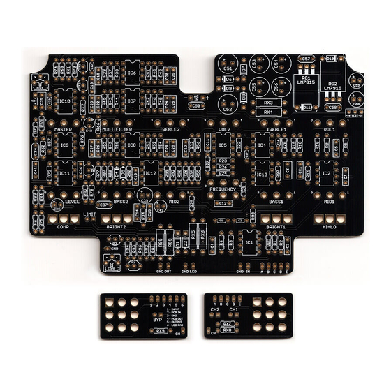
The regulators are very tall and cannot stand straight up due to the height of the enclosure. They must be
folded over with their heatsinks facing upwards. (See the photo of the populated PCB on the project page.)
Make sure that the heatsinks do not touch anything metal such as the enclosure or other components or it will
cause issues. There will be one diode underneath the metal fin of each of the folded-over regulators, but you
should have plenty of clearance for this. Make sure to fold the legs down close to the body or RG2 might touch
the edge of the enclosure.
Capacitor choice
(You can ignore this section if you're ordering the parts from Mouser, unless you're curious.) There isn't enough
space in the enclosure to use gigantic filter and booster capacitors in the power supply, so it's very important
that you choose the power supply capacitors carefully. The booster caps and filter caps should be rated for as
high of a ripple current as you can find. Ripple current is the maximum amount of current that can flow through
the cap before it overheats and fails, and if you run a capacitor at close to its maximum ripple current then
you shorten its life. None of these caps will see more than 120mA in practice, but the higher the ripple current
rating, the cooler a cap will stay, which greatly extends its life. Anything above 600mA max ripple current
should be fine, but higher is better. I found some that were 1600mA! Oftentimes these are categorized by the
manufacturer as "low ESR" or "low impedance" capacitors.
L5 PREAMP
8
