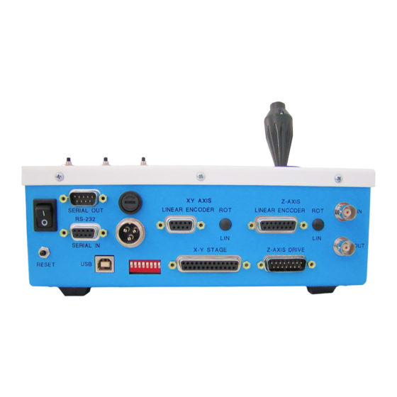
ASI MFC2000 Fonctionnement - Page 10
Parcourez en ligne ou téléchargez le pdf Fonctionnement pour {nom_de_la_catégorie} ASI MFC2000. ASI MFC2000 19 pages.

Last update: 2021/12/20 16:41
Constant Velocity Moves – (with firmware Version 8.1+)
The MS 2000 controller now uses a full closed loop trajectory driven algorithm for all commanded
moves. This means that the move velocity is controlled as part of the digital feedback loop. Many
users need to have high precision slow speed control. The MS 2000 now provides the smoothest
control possible in a motorized stage. To achieve this unsurpassed control, we have had to impose
some small restrictions in terms of the acceptable velocity values. The controller has a minimum
controlled speed of one encoder count per 64 servo cycles. The table below shows the slowest
controlled speed for various stage configurations:
6.35 mm Pitch Lead-
XY Stage:
0.5 ms servo
0.69 μm/sec
loop
XYZ Stage:
0.75 ms servo
0.46 μm/sec
loop
The controlled stage speed must be an integer-multiple of the minimum speed. For example, an XYZ
stage with 6.35 mm pitch lead-screw could be programmed to move 0.46 m/s, 0.92 m/s, 1.38 m/s,
etc., but not values between the integer-multiple of the slowest speed. Be aware that at the very
slowest speeds, the condition and cleanliness of the stage, and the calibration of the analog stage
driver circuitry can have a dramatic effect on the smoothness of operation. Please request tech note
TN120 Slow Speed Considerations for further information.
TTL Controlled I/O Functions
Buffered TTL input (IN0) and output (OUT0) are available on internal connector SV1 pins 1 & 2
respectively. These lines may be connected to the IN and OUT BNC connectors on the MS 2000 back
panel. The TTL command allows the user to select which functions are active for the IN0 and OUT0
lines. Various functions supported by the TTL command include:
Triggered moves or Z-stack acquisitions
Triggered asynchronous serial stage position reporting
Output pulses upon move completion
Output gated during constant speed motion.
The TTL input functions require the IN0_INT firmware module. The output functions are available in all
builds.
Automated 1-D or 2-D Scanning
Systems the with SCAN_MODULE firmware addition have some special commands that make raster
scanning very easy and well controlled. With the SCAN, SCANR, and SCANV commands, you can
define a raster area and the number of raster lines. The stage will scan each line at constant speed,
followed by rapid retrace. Hardware line sync signals available on SV1 pin 7 for the X or Y axis, as
selected by internal jumper JP1 (1&2 X-axis; 2&3 Y-axis). With the ENC_INT firmware module encoder
https://asiimaging.com/docs/
ms2000_operation
screw Stage
1.59 mm Pitch Lead-
screw Stage
0.17 μm/sec
0.12 μm/sec
https://asiimaging.com/docs/ms2000_operation
10nm resolution Linear
Encoder equipped Stage
0.31 μm/sec
0.21 μm/sec
Printed on 2022/03/16 04:45
