ASI MFC2000 Fonctionnement - Page 12
Parcourez en ligne ou téléchargez le pdf Fonctionnement pour {nom_de_la_catégorie} ASI MFC2000. ASI MFC2000 19 pages.

Last update: 2021/12/20 16:41
Default Settings, Saved Parameters, Configuration Flags,
Limits and Positions
The controller keeps track of several sets of flags, parameters and other saved configuration
variables. It is important to understand how changing some of these parameters affect the other sets.
The parameter sets are discussed below, starting with the most permanent settings and continuing to
the least permanent settings.
Motor Driver Alignment Parameters
The motor driver alignment parameters are set with the AA and AZ commands. These commands set
nonvolatile digital potentiometers located in the driver circuitry. These settings are independent of
the other parameters settings and are immediately saved on the digital pots themselves.
Configuration Flags
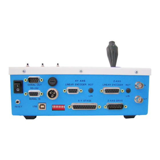
The configuration flags are set with the
and #6 (the DIP switches change between linear and rotary mode for the XY stage and Z-axis drive
respectively). The configuration flags allow the loaded firmware to work with a variety of specific
hardware configurations. Specific lead screw pitch, linear encoder resolution, encoder type, and piezo
Z-axis range are some examples of the configurations settings that can be changed. (See the CCA
command for details). The configuration flags are usually only changed when the controller is first set
up for a particular set of hardware, when new firmware is loaded using the ASI Updater, or when
changing between linear and rotary encoder for the stage. When a configuration flag is changed, it is
immediately saved in nonvolatile memory; the controller must be restarted for the new configuration
to be implemented.
Saved Parameters
There are many operating parameters that can be changed in the controller. These include such
things as error tolerances (E and PC commands), speed and acceleration times (S and AC commands),
servo parameters settings (KP, KI, and KD commands), and many others. All of these operating
parameters have Factory Default settings that have been determined to be appropriate for most
typical situations. A user may find that a change to some parameter value will improve the
performance of the system for their application. When parameter values are changed using a serial
command, the new parameter immediately becomes active in the controller. Third party software
vendors can change parameter settings "on the fly" using their software and the changes will remain
active as long as the controller remains powered on and not RESET. Parameter changes can be made
https://asiimaging.com/docs/
ms2000_operation
"CCA X=n"
Whenever any configuration flag is changed, the controller
restores any Saved Parameter settings back to the Factory
Defaults settings.
https://asiimaging.com/docs/ms2000_operation
command, and by the position of DIP Switches #3
Printed on 2022/03/16 04:45
