AMERITRON AL-1500 Buku Petunjuk - Halaman 5
Jelajahi secara online atau unduh pdf Buku Petunjuk untuk Penguat AMERITRON AL-1500. AMERITRON AL-1500 16 halaman. Full power linear amplifier

METERING FUNCTIONS
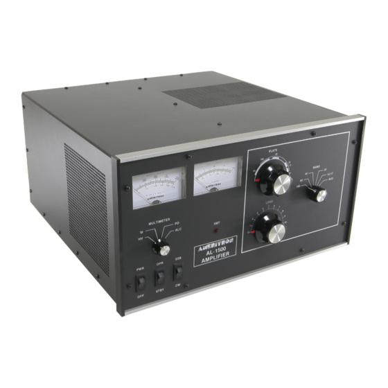
The AL-1500 has two illuminated meters. The Grid Current meter
provides a continuous indication of the 3CX1500/8877 grid
current. This exclusive feature of Ameritron amplifiers indicates
proper amplifier operation better than any other parameter. Do
not exceed 75 mA on this meter during normal operation of this
amplifier. The other meter reads Plate Voltage (HV), Plate
Current (IP), Peak RF Watts (PO) and ALC. These functions are
selected with the Multimeter Switch.
Plate Voltage (HV): Read DC Plate Voltage on the 4000 volt
scale. This scale is 100 volts per division. Normal voltages are
3600 volts no load, 3300 volts full load.
Plate Current (Ip): Read DC Plate Current on the 1000 mA scale.
This scale is 25 mA per division.
Peak RF Watts (PO): Read Peak RF Watts on the 2000 watt
scale. This scale has 50 watt divisions below 1000 watts and 100
watt divisions above 1000 watts.
NOTE:
This circuit uses an emitter follower to charge a
capacitor to the peak envelope voltage detected by the
ALC/Power Board. Accurate peak envelope power readings are
given when the amplifier is connected to a 50 ohm nonreactive
load. If the amplifier is used with a mismatched load, the power
meter will read higher or lower than normal by a ratio up to the
value of the SWR. Potentiometer
The high voltage present on the plate choke and air variable
capacitors attracts dust and dirt out of the air stream. It is
particularly important that the high voltage areas at the bottom of
the plate choke and the insulators on the air variable capacitors be
dust free. These areas should be inspected every few months if
the amplifier is operated in a dusty environment. Unplug the line
cord, and wait about 90 seconds until the power supply capacitors
discharge. Check the HV scale for zero voltage before removing
the cover. Remove the cover. You must first connect a jumper
wire from ground or chassis to the anode connection
TRANSFORMER INSTALLATION
Remove the cover of the amplifier. Remove the small package
that is wrapped around the anode connector. This is the fuse pack
and contains the fuses, fuse caps and the remainder of the chassis
screws. Remove the top 7/16" nuts from the four transformer
mounting bolts inside of the amplifier. Carefully remove the
transformer from its shipping carton.
Place the transformer on the four
because the transformer is heavy. The side with the two high
voltage secondary RED leads must be adjacent to
PERIODIC MAINTENANCE
the tubes.
of
INSTALLATION
1
/4-20 mounting bolts. Use care
R5 on the Meter Board (50-01140-1) adjusts the calibration of the
power meter.
ALC: Indicates a relative drive level (average, not PEP) that can
be estimated by dividing the Peak RF Watts scale by 10.
TECHNICAL ASSISTANCE
Technical assistance is available during our normal business
hours on weekdays. The following information is required to
assist you with operational problems:
1. Model and Serial Number
2. Date of purchase and dealer
3. An accurate description of the problem
Meter readings at all stages of the tuning proceedure are very
important along with a complete description of the other
equipment used with our product.
Written assistance is also available. Due to time delays in
processing mail, please allow at least three weeks for a writ
ten reply.
AMERITRON 116
Willow Road
Starkville, MS 39759
Tel: (662) 323-8211
Fax: (662) 323-6551
NOTE: This is a safety wire that must be installed when
beginning service work. After service is complete, reverse the
procedure to remove the safety wire. Remove the wire from the
anode connection first and then from ground.
Use a soft bristle brush dipped in alcohol to clean areas men-
tioned previously. In the event that cleaning is required at
frequent intervals, place a low restriction air filter material over
the air inlet holes on the left front side of the cabinet near the
filter capacitors. Most hardware stores stock suitable materials
that are used as replacement filters for window air conditioners.
the center panel(see Fig. 1). Now place a 7/16" nut on each bolt
(see Fig. 2). Snug the nuts down manually. Do not tighten with a
ratchet wrench.
1
Remove the brass
hex nuts and the top flat washer from the
/4"
two 6-32 screws on the rectifier board (see Fig. 1). Install the
RED lead ring terminals on the screws and replace the flat
1
washers and
hex nuts. Position the wires so that the black
/4"
insulated areas are at least
1
objects. Now tighten the
/4"
1
from each other and any metal
/4"
hex nuts.
