DoorHan SLIDING-2100 Panduan Instalasi dan Pengoperasian - Halaman 6
Jelajahi secara online atau unduh pdf Panduan Instalasi dan Pengoperasian untuk Pembuka Gerbang DoorHan SLIDING-2100. DoorHan SLIDING-2100 12 halaman. Drive
Juga untuk DoorHan SLIDING-2100: Panduan Instalasi dan Pengoperasian (16 halaman), Panduan Instalasi dan Pengoperasian (12 halaman)
Materials to install and related accessories (if any):
y cable 2 × 0,5 mm
y cable 4 × 0,5 mm
y cable 3 × 1,5 mm
y use cables with appropriate voltage insulation.
WARNING! ELECTRIC SHOCK HAZARD!
Cables of 220-240 V AC shall be installed by a qualified specialist. Cabling is carried out with protective channels, do
not allow cables and moving door elements contact. If the supply cable is damaged, it should be replaced by a related cable
4.3. Drive installation
Follow these rules to ensure safe and efficient operation of the drive:
y Door design shall provide the installation of automatic equipment.
y Soil shall be sufficiently firm and stable to mount the installation base for the drive.
y Foundation area shall be free from pipes or electrical cables.
y If the motor is not protected from passing transport, install the appropriate protection means to prevent from accidental
impact.
y Make sure of effective drive grounding.
1. Mount the drive on the base and set the desired distance between the drive gear and door by moving it. Secure the drive.
2. Release the drive.
3. Put protective cable tubes or channels through the holes in the base.
4. Attach the gear racks to the door horizontally (see pp. 4.4 or 4.5).
5. Set the desired gap between the gear rack and drive gear (~ 2 mm). The gear teeth shall be geared with the rack teeth along
the full width.
6. Move the door and make sure the gear rack does not put pressure on the gear and does not shift. Secure other rack sections.
7. Open the door and set the limit switch to open (see p. 4.6).
8. Close the door and set the limit switch to close (see p. 4.6).
9. Put the drive in gear.
10. Adjust the control unit (see p. 5).
11. Perform a test run and make sure of normal operation of the drive.
12. If necessary, adjust the position of the limit switches.
WARNING! Remove the breather screw after installing the drive.
6
(photocells transmitter, step-by-step control button);
2
(photocells receiver);
2
(power supply);
2
49
10
5 макс
max 5
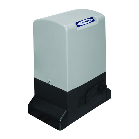
DRIVE ASSEMBLY