Asus AAEON PICO-APL1-SEMI Panduan Instalasi Cepat - Halaman 3
Jelajahi secara online atau unduh pdf Panduan Instalasi Cepat untuk Motherboard Asus AAEON PICO-APL1-SEMI. Asus AAEON PICO-APL1-SEMI 4 halaman.

Step 7: Insert the PICO-APL1 board into the
chassis assembly with the processor side toward
the heatsink. DO NOT place the CMOS battery
between the board and heatsink.
Step 9: Thread the power button cable through the hole for the power button. Plug the cable into the front panel
connector (CN3 in user manual). NOTE: The white dot indicates PIN 1 connector, make sure the connector is
properly aligned. Next, gently push the power button in until it is secure (you will hear a 'snap'). Be careful not to
tangle the power button cable with the CMOS battery cable.
Step 10: Peel the backing off of the tape on the CMOS battery. Gently press the battery onto the
PICO-APL1 board to secure it.
Step 11: Attach the bottom chassis by first lining up the right side, then swivel the chassis into place.
NOTE: the bottom chassis does not slide directly on, it must swivel into place as shown in the figure.
Step 12: Ensure the bottom chassis is properly lined up and attached. Use black screws to secure, two
screws on the bottom and one screw on the left and right sides of the chassis.
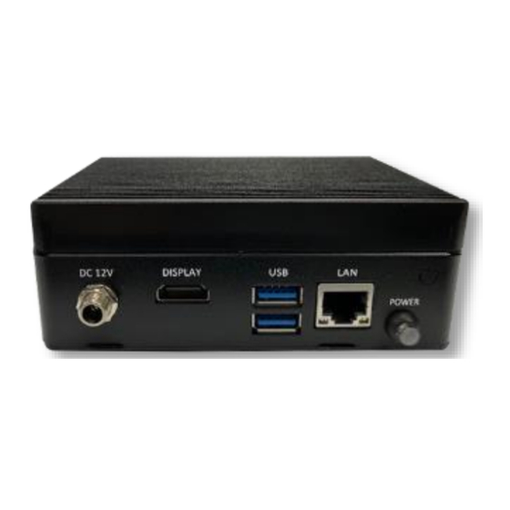
Step 8: Check that the I/O ports are properly
aligned. Secure board with four nickel screws.
