CommScope 2064184-1 Lembar Instruksi - Halaman 2
Jelajahi secara online atau unduh pdf Lembar Instruksi untuk Kabel dan konektor CommScope 2064184-1. CommScope 2064184-1 17 halaman. Fiber optic connector kits
3. SAFETY PRECAUTIONS
To avoid personal injury, ALWAYS wear eye
DANGER
protection when working with optical bers.
NEVER look into the end of terminated or
unterminated bers. Laser radiation is invisible
but can damage eye tissue. NEVER eat, drink, or
smoke when working with bers. This could lead
to ingestion of glass particles.
BE VERY CAREFUL to dispose o
DANGER
properly. The bers create slivers that can easily
puncture the skin and cause irritation.
DO NOT use defective or damaged components.
CAUTION
Replace them with new components.
!
4. REQUIRED TOOLS AND MATERIALS
— Cable Holder Assembly 1278023--1 or
2064540--1
— Miller Strip Tool 1754708--1
— Alcohol Fiber Wipe Packet 501857--2
— isopropyl alcohol
— Fiber Optic Cleaver 1871696--1 (408--10086)
— LightCrimp Plus SC Die Set with Crimping Tool
492782--1 (consists of Die Set 492783--1 and
PRO--CRIMPER® III Hand Tool 2064431--1)
Can be used for terminating all ber and cable.
— LightCrimp® Inline Splice Die Set with Crimping
Tool 2064603--1 (consists of Die Set 1985766--1
and PRO--CRIMPER III Hand Tool 2064431--1)
Can only be used for terminating 900- - m m
bare bu ered ber, 250 --m m coated ber, and
1.6- - to 2.0- - mm jacketed cable.
2 of 17
5. ASSEMBLY PROCEDURE
900-m m Bare Bu ered Fiber
5.1.
ber ends
Termination
Cover
Connector kit is shipped with these installed onto connector
assembly. Keep them in place until ready for assembly.
A. Preparing 900-mm Bare Bu ered Fiber
1. Slide the bare bu er boot (small diameter end
rst) over the bu er. See Figure 2, Detail A.
2. Remove the plunger dust cap from the
connector assembly, and discard.
3. Push the connector assembly into the holder of
the cable holder assembly with the termination
cover facing outward. See Figure 2, Detail B. Make
sure that the connector butts against the lip on the
arm of the cable holder assembly. Slide the ber
into the channel marked "BUFFER". Make sure
that the tip of the bu er butts against the end of the
channel.
4. Mark the bu er at each cross--slot of the
channel. See Figure 2, Detail B. Remove the bu er
from the cable holder assembly.
5. Using the strip tool, strip the ber to the rst
mark. It is recommended holding the strip tool at
an angle to the ber and stripping the ber in three
sections. See Figure 2, Detail C. Clean the ber
with an alcohol ber wipe to remove the ber
coating residue.
CAUTION
!
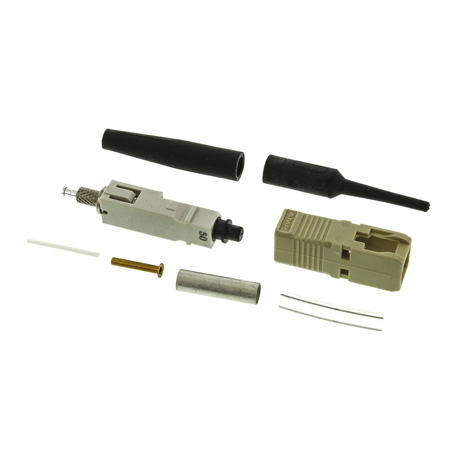
Kit Components Required
(Discard Other Components)
Plunger
Dust Cap
Connector
Assembly
Before using the strip tool, make sure that the "V"
opening is clean; otherwise the ber could break.
Only use isopropyl alcohol on the tool.
408- 4471
Bare Bu er
Boot
Connector
Housing
(Figure 2)
Rev N