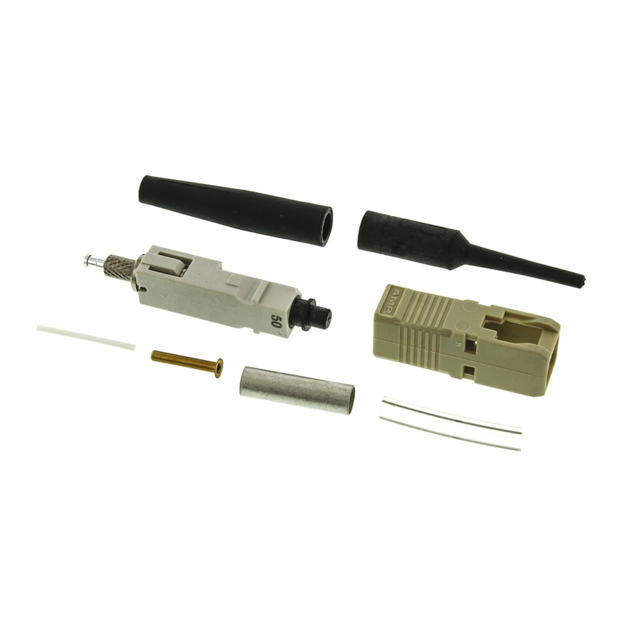
CommScope 2064184-1 Lembar Instruksi - Halaman 3
Jelajahi secara online atau unduh pdf Lembar Instruksi untuk Kabel dan konektor CommScope 2064184-1. CommScope 2064184-1 17 halaman. Fiber optic connector kits

B. Cleaving
(Figure 3)
1. Open the ber clamp of the ber optic cleaver.
Press the button, and slide the carriage back
(toward the ber clamp). Then move the ber slide
back until it stops.
2. Place the stripped ber into the slot so that the
end of the bu er is at the 8--mm marking. See
Figure 3, Detail A.
3. While applying pressure on the bu er, carefully
slide the ber slide forward (toward the carriage)
until it stops. See Figure 3, Detail B.
4. Gently close the ber clamp, and slide the
carriage forward. DO NOT touch the button while
sliding the carriage. See Figure 3, Detail C.
5. Open the ber clamp, and move the ber slide
back until it stops.
6. Remove the cleaved ber, and properly dispose
of the scrap ber.
DO NOT attempt to clean the ber after it has
CAUTION
been cleaved.
!
C. Crimping
(Figures 4 and 5)
1. Open the cable clamp of the cable holder
assembly, and position the bu er (with the cleaved
end facing the connector) inside the clamp. Move
the bu er so that the end of the ber is even with
the front of the arm of the cable holder assembly,
and holding the bu er in place, close the clamp.
See Figure 4, Detail A.
2. Carefully insert the ber into the plunger of the
connector assembly until the ber bottoms against
the internal ber. Make sure that the remaining
mark on the bu er enters the plunger. The
resultant bend in the bu er should hold the ber
against the internal ber. See Figure 4, Detail B.
It is important that the ber bottoms against, and
NOTE
remains against, the internal ber. If the mark
i
does not enter the plunger or if the ber does not
seem to bottom against the internal ber, the
ber may be caught on internal guides. Rotating
the connector and backing the ber out a small
amount and re--entering may help. However, if
the mark will not enter the plunger, the ber must
be re--stripped.
Make sure that the ber does not pull rearward
from the contact (with the internal ber) during
the crimping operation.
3. If using Die Set 492783--1, remove (and retain)
the termination cover.
If using Die Set 1985766--1, do not remove the
termination cover.
Rev N
4. Squeeze the handles of the hand tool until the
ratchet releases. Allow the handles to open fully.
Then:
If using Die Set 492783--1, slowly close the
handles until you hear 2 clicks from the ratchet.
If using Die Set 1985766--1, slowly close the
handles until you hear 3 clicks from the ratchet.
5. With the connector assembly in the cable holder
assembly, position the ferrule or termination cover
in the upper cavity of the front die and the plunger
in the upper cavity of the rear die. See Figure 4,
Detail C.
The arrows marked on the front die indicate the
CAUTION
direction that the ferrule or termination cover
!
must be pointing when the connector is
positioned in that cavity. For proper placement,
and to avoid damage to the ber, observe the
direction of the arrows. Refer to Figure 4, Detail
C and Figure 5, Detail A.
6. Gently push the bu er toward the connector
assembly to make sure that the ber is still
bottomed, then slowly squeeze the tool handles
together until the ratchet releases. Allow the
handles to open fully, and remove connector from
the dies.
7. Position the plunger of the connector assembly
in the rst (smallest) cavity of the front die with the
knurl against the edge of the groove in the die and
the ferrule or termination cover pointing in the
direction of the arrow. See Figure 5, Detail A.
8. Slowly squeeze the tool handles together until
the ratchet releases. Allow the handles to open
fully, and remove the connector assembly from the
die.
9. Slide the bare bu er boot over the plunger until
the boot butts against the connector assembly. See
Figure 5, Detail B.
10. Remove the connector assembly from the
cable holder assembly.
11. Align the key of the connector housing with the
chamfered edges of the connector assembly. Slide
the housing over the assembly until it snaps in
place. See Figure 5, Detail C.
DO NOT force the components together. They
NOTE
are designed to t only one way.
i
The assembly procedure for 900--mm bare bu ered
ber is now complete.
If connecting connectors, refer to Paragraph 5.5.
"
408- 4471
3 of 17
