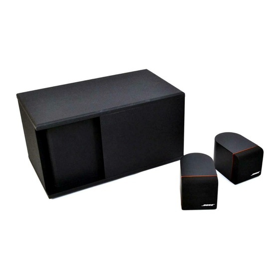
Bose Acoustimass 3 Series Panduan Servis - Halaman 10
Jelajahi secara online atau unduh pdf Panduan Servis untuk Sistem stereo Bose Acoustimass 3 Series. Bose Acoustimass 3 Series 42 halaman. Powered speaker system
Juga untuk Bose Acoustimass 3 Series: Panduan Pemilik (17 halaman), Panduan Pemilik (10 halaman), Manual (43 halaman)

8. Auto Turn-On/Off Mute
An improved version of auto turn-on/off is used in the AM-3P. A separate 3.5 mm stereo mini-
jack (J7) is used to receive the turn-on signal from the serial data output of the Lifestyle music
center. When the 3.5 mm plug is inserted, the audio sense circuit is disabled and the amplifier
outputs will only unmute if the DC control signal is present at J7 pin 3. This action occurs
through the built-in DPDT switch in J7 which connects J7 pin 3 directly to the Q9 mute circuit.
Therefore, the system is not subject to random false turn-on (from electrical noise, etc.) when
used with the Lifestyle music center.
When the AM-3P is used with a source other than the Lifestyle music center,the stereo mini-
plug is not inserted into the jack, and therefore mute transistor Q9 is directed to the output of
the audio detect comparator U6 (pin 5,6,7). This comparator uses hysteresis to achieve a
positive turn-on of at least 90 seconds before the system will revert to stand-by (mute) mode
after removal of the audio signal.
9. Compressor Detect
The output of each left/right amplifier is half-wave detected through diodes D108 and 208. This
voltage is divided down by R53 and R54 and presented at the emitter of Q12. Power supply
voltage is similarly divided down by R50 and R51 and presented at the base of Q12. Diodes
D13 and D14 simulate the saturation voltage drop that occurs in the power amp stage.
Therefore, when the audio output of any amplifier comes within 2 volts of the instantaneous
power supply voltage, Q12 will conduct.This signals the compressor (limiter) to act. Current
from Q12 charges hold capacitor C35 and releases capacitor C36. Voltage at C35 is buffered
by transistor U1 (pins 5,6,7) and decreased down to a logarithmic voltage by resistor R67 and
diode U1 (pins 12,13,14). This voltage is then presented to the base of compressor transistors
U1 (pins 1,2,3) and U1 (pins 8,9,10) which are described in the compressor section.
The DC control voltage present across capacitor C35 is derived through the use of an improved
hold and release characteristic, resulting in lower compressor distortion. In conventional
limiters, this DC control voltage is derived by a simple series diode and parallel RC network to
ground. Unfortunately, for low frequency overload, this results in substantial ripple voltage
present on the DC gain control voltage. This results in the all too common problem of mid-range
voices or instruments being badly "modulated" by low frequency overload. This problem is
solved by having two separate capacitors, one that "holds" the smooth DC voltage just long
enough to prevent low frequency ripple (approximately 40ms) and the other (C36) which quickly
releases the hold capacitor (through diode D17) at the proper time to maintain overall 100ms
release time.
9
