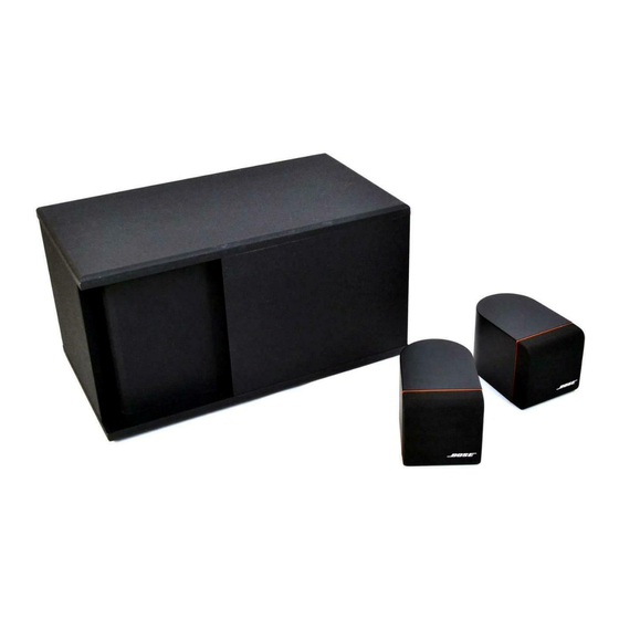
Bose Acoustimass 3 Series Panduan Servis - Halaman 8
Jelajahi secara online atau unduh pdf Panduan Servis untuk Sistem stereo Bose Acoustimass 3 Series. Bose Acoustimass 3 Series 42 halaman. Powered speaker system
Juga untuk Bose Acoustimass 3 Series: Panduan Pemilik (17 halaman), Panduan Pemilik (10 halaman), Manual (43 halaman)

A non-serviceable thermal fuse is located inside the transformer to limit the maximum
temperature to 145 °C under abnormal conditions. However, in most cases the external fuse
(F1) should fail before the internal transformer thermal fuse. The thermal fuse can be checked
by measuring the continuity between pins 1 and 4 (black and white wire) of the primary
connector. This connector is located on the Equalizer PCB.
2. Differential Input Stage
Audio input applied at the phono jack (J8) connects directly to the right (left) differential amplifier
buffer. This stage accomplishes several functions:
- Provides rejection of common-mode interference (such as hum) that might be picked up
by the long audio cable between the AM-3P and lifestyle music center
- Provides input overload and ESD protection through diodes (D101-104)
- Removes radio frequency Interference through C103,125,127
- Provides DC blockage by C101,102
- Provides a 6 dB gain through op-amp U101.
3. Compressor/Treble Stage
U102 (pins 1,2,3), with potentiometer VR2 at the center position, operates as a conventional
inverting operational amplifier stage with a gain of 6 dB. However, when voltage overload is
present at the speaker outputs, transistor array U1 (pins 1,2,3) receives a turn-on signal from
the compressor detect stage. Under this condition, the transistor acts as a variable resistor
to ground, and with R107, forms a resistor divider network that attenuates the audio signal.
The amount of attenuation and timing action is carefully controlled by the compressor detect
stage (to be discussed later).
Potentiometer VR2 adjusts the amount of treble boost or cut. In the full counterclockwise
position, the wiper (pin 4) shorts to pin 1. The maximum boost and cut frequency response
graph is shown in Figure 2 on page 4.
4. High Frequency (HF) Equalization
High frequency equalization and crossover is achieved through three cascaded active EQ
stages. These stages consist of U103,U104 and U105. The purpose of equalization is two-
fold:
- It provides very sharp low frequency attenuation below 200 Hz (the crossover frequency)
to prevent overload of the L/R speakers
- It provides finely tailored correction in the speaker pass-band so that overall frequency
response of the system is acoustically correct.
7
