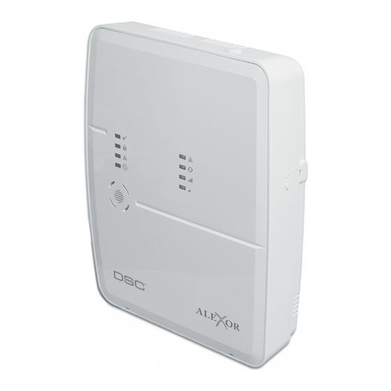
DSC WT5500 Panduan Petunjuk Instalasi - Halaman 2
Jelajahi secara online atau unduh pdf Panduan Petunjuk Instalasi untuk Panel Kontrol DSC WT5500. DSC WT5500 8 halaman. Wireless panel & keypad
Juga untuk DSC WT5500: Panduan Instalasi Mulai Cepat (2 halaman)

English
Installation Instructions
The WT5500 keypad can be used on security systems with up to 64
zones. The WT5500 keypad is compatible with the SI9155 system.
Specifications
• Temperature range: -6°C to +54°C (22°F to 140°F), Temperature
range for UL/ULC: 0°C to +49°C (32°F to 120°F)
• Humidity (MAX): 93%R.H.
• Plastic enclosure protection degree: IP30, IK04
• Transformer voltage: 4.5V @ 0.5A
• Battery: 3V
• WT5500 Current draw: 50mA (standby)/125mA (maximum)
• Wall mount tamper
• 5 programmable function keys
• Ready (Green LED), Armed (Red LED), Trouble (Yellow LED), AC (Green
LED)
• Frequency: 433.92MHz (WT5500-433 only)
• Frequency: 868.35MHz (WT5500-868 only)
Unpacking
The WT5500 keypad package is available in five distinct configurations,
Standard, Proximity, Complete, Desk Stand, and Proximity Tags Only. The
contents of each are described below.
WT5500 - STANDARD
WT5500P - PROXIMITY
•1 WT5500 keypad
•1 WT5500P keypad
•1 WT5500BRK wall bracket
•1 WT5500BRK wall bracket
•1 Installation manual
•1 Installation manual
•1 Inner door sticker
•1 Inner door sticker
•4 AA batteries
•4 AA batteries
•1 Hardware pack
•1 Hardware pack
•1 PT4 (433MHz proximity tag) or
PT8 (868MHz proximity tag)
WT5500D - COMPLETE
WT5500DMK - DESK STAND
•1 WT5500 keypad
•1 WT5500DMK keypad
•1 WT5500X AC transformer
•1 WT5500X AC transformer
•1 WT5500DMK desk stand
•1 Installation manual
•1 WT5500BRK wall bracket
•1 Hardware pack
•1 Installation manual
•1 Inner door sticker
•4 AA batteries
•1 Hardware pack
PROXIMITY TAGS ONLY
•1 PT4 (433MHz proximity tag) or
PT8 (868MHz proximity tag)
•1 Installation manual
Mounting
You should mount the keypad where it is accessible from designated points
of entry and exit. Once you have selected a dry and secure location, perform
the following steps to mount the keypad.
Mounting Plate
1. Locate the screw holes (4) at each corner of the mounting plate.
Screw
Holes
Mounting
Tabs
Screw
Holes
9049
2. With the smooth face of the mounting plate facing up, use the four screws
provided to affix the mounting plate to the wall.
3. Align the four mounting slots in the WT5500 housing with the four
mounting tabs protruding from the mounting plate.
4. Slide the unit into place.
5. Firmly but carefully snap the unit down onto the mounting plate.
Desk Stand
1. Place the desk stand on a secure, uncluttered surface.
2. Align the four mounting slots in the WT5500 housing with the four
mounting tabs protruding from the desk stand.
3. Slide the unit into place.
4. Firmly but carefully snap the unit down onto the desk stand.
Apply Battery Power
1. Slide the unit up and out from the mounting plate. The bay for the four AA
batteries is open and clearly visible at the back of the unit.
Tamper
Switch
Batteries
Screw
Holes
9048
2. Insert the batteries as directed on the unit.
3. Replace the unit on the mounting plate.
Apply AC Power
1. Slide the unit up and out from the mounting plate.
Screw
2. Locate the AC adaptor jack at the back of the unit housing.
Holes
3. Place the AC adaptor plug in the housing indentation, perpendicular to the
unit. Insert the adaptor plug firmly into the jack.
4. Pivot the adaptor plug downwards so that it fits flush with the housing.
Guide the AC wire along the channel provided in the unit housing; the wire
should finally extend through the bottom of the housing.
5. Replace the unit on the mounting plate.
6. Plug the AC adaptor into a wall outlet.
Programming the Keypad
There are several programming options available for the keypad. These are
described below. Programming the keypad is similar to programming the
rest of the system. To turn an option on or off, press the number correspond-
ing to the option on the number pad. The numbers of the options that are
currently turned on will be displayed along the top of the LCD. For informa-
tion on programming the rest of your security system, please refer to your
system's Installation Manual.
Broadcasting LCD Labels
All LCD programming is done using the keypad. If more than one LCD key-
pad is present on the system, labels programmed at one keypad can be
broadcast to all other LCD keypads. Perform the following procedure in order
to broadcast labels:
1. Program one LCD keypad completely.
Mounting
Holes
Plug
Wire
Channel
Mounting
Holes
