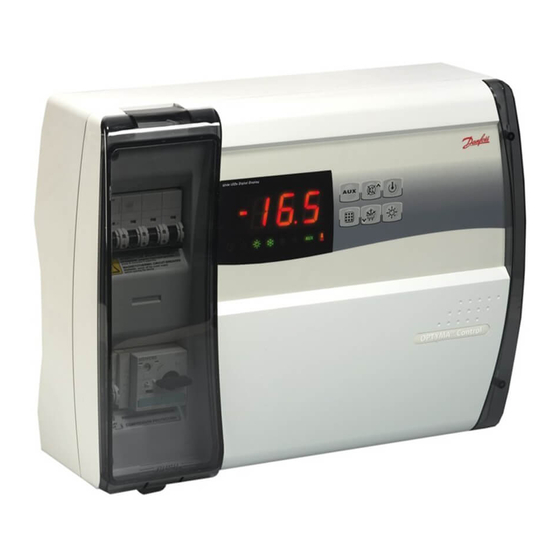
Danfoss AK-RC 111 Panduan Pengguna - Halaman 8
Jelajahi secara online atau unduh pdf Panduan Pengguna untuk Unit Kontrol Danfoss AK-RC 111. Danfoss AK-RC 111 16 halaman. Single phase

User Guide | Optyma™ control AK-RC 111 single phase
4.4 General
4.5 Key to symbols
4.6 Setting and displaying the
set points
4.7 Level 1 programming
(user level)
4.8 List of Level 1 variables
(user level)
8 | BC309238530328en-000101
To enhance safety and simplify the operator's work, the AK-RC 111 has two programming levels; the
first level (Level 1) is used to configure the frequently-modified SETPOINT parameters. The second
programming level (Level 2) is for general parameter programming of the various controller work
modes.
It is not possible to access the Level 2 programming directly from Level 1: you must exit the
programming mode first.
For purposes of practicality the following symbols are used:
() the UP key
is used to increase values and mute the alarm.
() the DOWN key
is used to decrease values and force defrosting.
1. Press the SET key to display the current SETPOINT (temperature).
2. Hold down the SET key and press the () or () keys to modify the SETPOINT.
Release the SET key to return to cold room temperature display: the new setting will be saved
automatically.
To gain access to the Level 1 configuration menu proceed as follows:
1. Press the () and () keys simultaneously and keep them pressed for a few seconds until the first
programming variable appears on the display.
2. Release the () and () keys.
3. Select the variable to be modified using the () or () key.
4. When the variable has been selected it is possible:
• to display the setting by pressing SET key.
• to modify the setting by pressing the SET key together with the () or () key.
When configuration values have been set you can exit the menu by pressing the () or () keys
simultaneously for a few seconds until the cold room temperature reappears.
5. The new settings are saved automatically when you exit the configuration menu.
Variables Meaning
Temperature difference compared to main SETPOINT
r0
d0
Defrost interval (hours)
If d0 = 0 cyclical defrosts Off
End-of-defrost setpoint
d2
Defrost is not executed if the temperature read by the defrost
sensor is greater than d2.
(If the sensor is faulty defrost is stopped on time set by the d3
parameter)
d3
Max defrost duration (minutes)
d7
Drip duration (minutes)
At the end of defrost the compressor and fans remain at standstill
for time d7, the defrost LED on the front panel flashes.
F5
Fan pause after defrost (minutes)
Allows fans to be kept at standstill for a time F5 after dripping. This
time begins at the end of dripping. If no dripping has been set the
fan pause starts directly at the end of defrost.
A1
Minimum temperature alarm
Allows user to define a minimum temperature for the room being
refrigerated. Below value A1 an alarm trips: the alarm LED flashes,
displayed temperature flashes and the buzzer sounds to indicate
the problem.
A2
Maximum temperature alarm
Allows user to define a maximum temperature for the room being
refrigerated. Above value A2 an alarm trips: the alarm LED flashes,
displayed temperature flashes and the buzzer sounds to indicate
the problem.
tEu
Evaporator sensor temperature display
(displays nothing if dE =1)
Value
Default
0.2 – 10 °C
2 °C
0 – 24 hours
4 hours
-35 – 45 °C
15 °C
1 – 240 min
25 min
0 – 10 min
0 min
0 – 10 min
0 min
-45 – (A2-1) °C
-45 °C
(A1+1) – 99 °C
99 °C
evaporator
read only
temperature
© Danfoss | DCS (vt) | 2020.03
