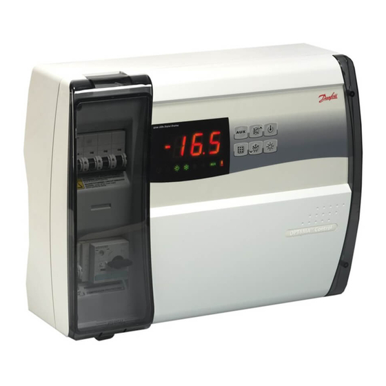
Danfoss AK-RC 111 Panduan Pengguna - Halaman 9
Jelajahi secara online atau unduh pdf Panduan Pengguna untuk Unit Kontrol Danfoss AK-RC 111. Danfoss AK-RC 111 16 halaman. Single phase

User Guide | Optyma™ control AK-RC 111 single phase
4.9 Level 2 programming
(installer level)
4.10 List of Level 2 variables
(installer level)
© Danfoss | DCS (vt) | 2020.03
To access the second programming level press the UP () and DOWN () keys and the LIGHT key
simultaneously for a few seconds.
When the first programming variable appears the system automatically goes to stand-by.
1. Select the variable to be modified by pressing the UP () and DOWN () keys.
When the parameter has been selected it is possible to:
2. View the setting by pressing the SET key.
3. Modify the setting by holding the SET key down and pressing the () or () key.
4. When configuration settings have been completed you can exit the menu by pressing the () and
() keys simultaneously and keeping them pressed until the room temperature reappears.
5. Changes are saved automatically when you exit the configuration menu.
6. Press the STAND-BY key to enable electronic control.
Variables Meaning
Fan status with compressor off
F3
Fan pause during defrost
F4
F6
Evaporator fans activation for air recirculation.
The fans activate for a time defined by F7 if they have
not started working for the F6 time. If activation time
coincides with the defrosting time, end of defrosting
is awaited.
F7
Evaporator fans duration for air recirculation.
Fans working time for F6
dE
Sensor presence
If the evaporator sensor is disabled defrosts are
carried out cyclically with period d0: defrosting ends
when an external device trips and closes the remote
defrost contact or when time d3 expires.
d1
Defrost type, cycle inversion (hot gas) or with heater
elements
dPo
Defrost at Power On
dSE
Smart defrost
Smart defrost Setpoint (if dSE=1)
dSt
The counting of the time between the defrost is
incremented only if the compressor is ON and the
evaporator temperature is less than dSt.
Display viewing during Defrost
dFd
Ad
Modbus Network address
Bdr
Modbus baudrate
Prt
Modbus parity check
Ald
Minimum and maximum temperature
signalling and alarm display delay
C1
Minimum time between shutdown and subsequent
switching on of the compressor.
CAL
Cold room sensor value correction
Value
0 = Fans run continuously
1 = Fans only run when
compressor is working
2 = Fans disabled
0 = Fans run during defrost
1 = Fans do not run during
defrost
0 – 240 min
0 = (function not activated)
0 – 240 sec
0 = evaporator sensor present
1 = no evaporator sensor
0 = heating element
1 = hot gas
2 = heater with
temperature control
0 = disabled
1 = defrost at power-on
(if possible)
0 = disabled
1 = enabled
-30 – 30 °C
0 = current temperature
1 = temperature at the
start of the defrost
2 = "DEF"
0 – 247
0 = 300 baud
1 = 600 baud
2 = 1200 baud
3 = 2400 baud
4 = 4800 baud
5 = 9600 baud
6 = 14400 baud
7 = 19200 baud
8 = 38400 baud
0 = none
1 = even
2 = odd
0 – 240 min
0 – 15 min
-10 – 10 °C
BC309238530328en-000101 | 9
Default
1
1
0 min
10 sec
0
0
0
0
1 °C
1
0
8
1
120 min
0 min
0 °C
