2easy DT-RLC Panduan Pengguna - Halaman 3
Jelajahi secara online atau unduh pdf Panduan Pengguna untuk Pengontrol 2easy DT-RLC. 2easy DT-RLC 11 halaman. Relay actuator

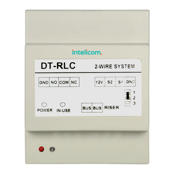
NC:The normally-closed contact to COM.
COM: The common contact of the unlock/light relay.
NO: The normally-open contact to COM.
Lock Control Jumper: To select the lock type:
POWER:Working indicator, it will light up when plugs in power supply.
IN-USE:Unlock/light indicator, it will light up when unlock(or turn on the light).
Bus:Connect to the bus line, no polarity.
DIP :Used for setting the address of the RLC.
3. Unit Mounting
DT-RLC
GND NO COM NC
POWER
IN-USE
DIN Rail Mounting
4. How To Set The Work Mode
Note that the factory default is lock control mode.
1).In DIP1 = ON, DIP2 = ON, DIP3 = OFF status, exit button(S1 and GND) short-
circuit, meanwhile, the DT-RLC will power-on to activate the setting mode;
2).In setting status, struck repeatedly DIP1 four times to switch work modes:
A.When the IN-USE indicator flashes once, it means the system will enter the lock
control mode.
B.When the IN-USE indicator flashes two times, it means the system will enter the
light control mode.
3).When the setting complete,it will automatically restart.
Please note the setting state valid within 5 seconds, more than five seconds without
operation, it will exit the setting mode automatically.
2-WIRE SYSTEM
12V S2
S1 GND
1
2
3
BUS BUS RISER
see section 5.3, 5.4.
-2-
