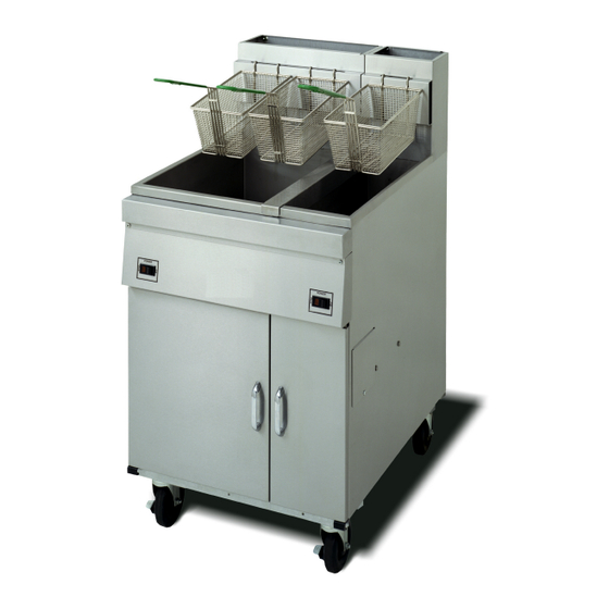
Dean Cool Zone Series Panduan Pemasangan, Pengoperasian & Pemeliharaan - Halaman 6
Jelajahi secara online atau unduh pdf Panduan Pemasangan, Pengoperasian & Pemeliharaan untuk Penggorengan Dean Cool Zone Series. Dean Cool Zone Series 19 halaman.

3. INSTALLATION
3.1 POSITIONING:
a. Initial Installation:
legs, do not push against any unit edges
to adjust its position. Use a pallet or lift
jack to lift it slightly and place it where
it is to be installed.
b. Relocating The Fryer: If relocating a
fryer installed with legs, remove all
weight from each leg before moving.
Note:
If a leg becomes damaged during
movement, contact your service agent
for immediate repair/replacement of that
leg.
DANGER!
THIS FRYER MAY TIP AND
CAUSE PERSONAL INJURY IF
NOT SECURED CORRECTLY IN
A
STATIONARY
REMOVE
ALL
BEFORE MOVING FRYER AS IT
MAY CAUSE SEVERE BURNS
UPON CONTACT.
3.2 LEG AND CASTER INSTALLATION:
a. General:
1.
Install legs and optional rear rigid
casters near where the fryer is to be
used, as neither are secure for long
transit.
mounted and must be equipped with
the legs (or legs and optional rigid
casters) provided.
2.
When positioning the fryer, gently
lower the fryer into position to
prevent undue strain to the legs and
internal mounting hardware. Use a
pallet or lift jack to lift and position
the fryer if possible.
fryer may damage the legs.
If installed with
POSITION.
SHORTENING
Unit cannot be curb
Tilting the
3. If the optional rigid casters are to be
installed on single fryers, the casters must
be installed on the fryer rear channel
assembly only.
4. Proceed to Step 3.3, Leveling, after legs
and/or optional rear rigid casters are
installed to ensure the fryer is level
before using.
b. Leg Installation:
1. Remove unit from pallet.
2. Carefully raise unit with forklift, pallet
jack, or other steady means.
3. Place one lock washer on each hex head
screw.
4. Insert hex head screws with lockwashers
(1/4-20 threads by 19mm (¾") long)
through bolt holes of leg mounting plates
as shown in the Figure 3-1 on the next
page. A locknut has been attached to the
topside of the mounting plate at the
factory to capture the hex head screw as
it is screwed in.
5. Tighten the bolts and nuts to 5.65 joules
(50 inch-lbs.) minimum torque.
For leg and caster installations, the unit
must be at room temperature and drained of
shortening before installing the legs and/or
casters.
c. Installing Optional Rear Rigid Casters:
1. Install rear rigid casters only at the rear
of the single fryer as shown in the Figure
3-1. Legs must be installed at the front
of the fryer.
2. Follow the same instructions for leg
installations as given above in steps
3.2.b.1-5.
5
CAUTION
