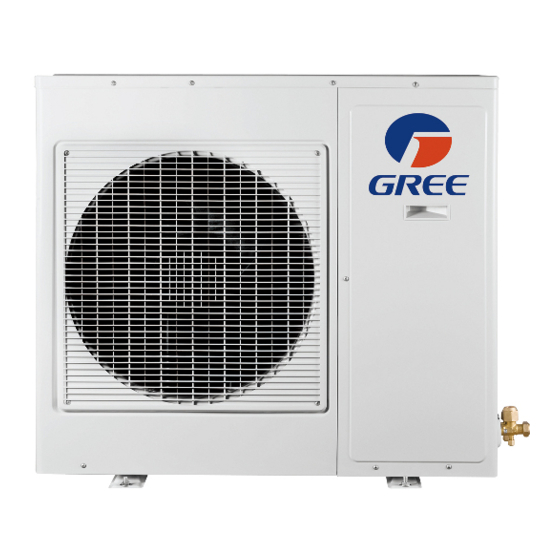
Gree GWHD(24)ND3CO Panduan Instalasi - Halaman 12
Jelajahi secara online atau unduh pdf Panduan Instalasi untuk Pompa Panas Gree GWHD(24)ND3CO. Gree GWHD(24)ND3CO 16 halaman. Multi
ductless inverter
Juga untuk Gree GWHD(24)ND3CO: Panduan Pemilik (11 halaman)

- 1. Heat Pump
- 2. Installation Manual
- 3. Table of Contents
- 4. Safety Precautions
- 5. System Requirements
- 6. Suggested Tools
- 7. Site Instructions
- 8. Dimensions
- 9. Indoor Unit
- 10. Outdoor Unit
- 11. Refrigerant Piping
- 12. Refrigerant Piping
- 13. Power and Wiring
- 14. Vacuum Testing
- 15. Start-Up
- 16. Troubleshooting
INSTALLATION OF POWER AND WIRING
Step 9 (Cont'd)
Multiple Port Wiring Diagram
6. Tightly connect main power wires to outdoor unit terminal block per wiring diagram above.
7. Secure all wires inside wire clamp/strain reliefs.Verify wires are secure, not loose and no
external force on wires affects the connections at the terminals.
8. Replace service panel on right side of the outdoor unit.
9. Connect main power wires and conduit to unit. Disconnect switch box per manufacturer's
instructions, National Electrical Code (NEC) and local electrical codes.
C UTION
• Electrical disconnecting means must be provided and shall be located
within sight and readily accessible from the unit.
• Failure to follow this caution may result in equipment damage or
improper operation.
• All wires running from the indoor to outdoor unit must comply with
National Electrical Code (NEC) and local codes.
• No wire should be allowed to touch refrigerant tubing, compressor or
any moving parts.
• All wires must be connected firmly to terminal block to avoid unit
malfunction, overheating and possible fire hazard.
(Reference Only)
INSTALLATION OF POWER AND WIRING
Local codes may require a disconnect switch within sight of the indoor unit. Use a DFS Disconnect
Switch Accessory Kit (Part No: DFS-SWITCH-A) to break wires going to the N(1), 2, 3, terminals on
the indoor unit, as shown in the wiring diagram below:
C UTION
Never break or interrupt the ground wire with a switch or disconnect device.
Setting Master-Slave Indoor Units
Typically, the outdoor unit will respond to the indoor units on a first-come-first-served basis.A single
indoor unit may be programmed at the master zone.The master zone will always have priority over the
other indoor units. Setting an indoor unit as the master zone is not required for system operation.
To set an indoor unit as a master zone, locate master/slave configuration switches on the outdoor main
control board.The switch locations 1, 2, 3, 4, 5 correspond to Indoor units (or Ports) 1, 2, 3, 4, 5. Select the
master zone by setting the desired switch to the "On" position.The other switches need to be set in the
"Off" for slaves. By turning the switch from number to ON, the IDU with ON is set to be the master unit.
NOTE: This function is not valid on the 18,000 BtuH 2-Zone model.
21
22
