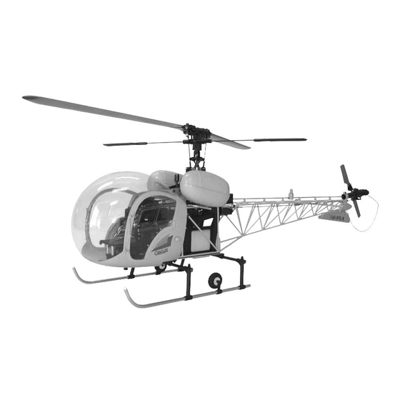
Century Helicopter Products Bell 47G II ARF Helicopter Manual - Halaman 10
Jelajahi secara online atau unduh pdf Manual untuk Mainan Century Helicopter Products Bell 47G II ARF Helicopter. Century Helicopter Products Bell 47G II ARF Helicopter 15 halaman.

STEP 12 Landing Gear
STEP 12 Landing Gear
STEP 12 Landing Gear
STEP 12 Landing Gear
STEP 12 Landing Gear
Insert all the M3x4 Set Screws into the landing gear components. Slide two landing gear mounts onto the straight
struts and align to the hole spacing on the lower side frames, notice that the rear mount face backwards and the
front mounts are forward. Once centered, verify both are level and secured by tightening the M3x4 Set
Screw on each mount. Slide the plastic vertical struts onto the ends of the straight struts, notice that the
vertical struts should slant forward and insert the aluminum skids from the front to the rear, positioning
the wheel mount inbetween. Position the end of the aluminum skid 15mm past the end of the rear strut
and tighten the M3x4mm Set Screws at the bottom. Before tightening any other set screws, measure the
distance between the aluminum skids at the back and front, slide the vertical struts to match the distances.
Lay the mechanics onto the landing gear mounts and position the front strut assembly to align the holes.
Finally, tighten all the remaining M3x4 Set Screws to lock the landing gear in place. Bond the skid caps in
place with CA or epoxy. Attach the wheels with two M3x15 Socket Cap Screws.
Aluminum
Skids x 2
[CN1074-19]
STEP 13 Truss & Rudder Mounts
STEP 13 Truss & Rudder Mounts
STEP 13 Truss & Rudder Mounts
STEP 13 Truss & Rudder Mounts
STEP 13 Truss & Rudder Mounts
Insert two M3x40 Socket Cap Screws through
one tail truss mount, through the main mechanics
and slide the rudder servo mount and the second
tail truss mount from the other side. Secure with
two M3 Locknuts.
Tail Truss
Assembly
[CN1074-10]
Vertical
Struts x 4
Landing Struts
[CN1074-20]
M3x4 Set
Screws x 14
Aluminum
Skids x 2
M3x12 Self
Tapping
Screws x 4
Landing Gear
Mounts x 4
Tail Truss
Mount x 2
[CN1074-11]
Rudder Servo
Mount
[HW3116]
STEP 14 Mounting Tail Truss & Mechanics
STEP 14 Mounting Tail Truss & Mechanics
STEP 14 Mounting Tail Truss & Mechanics
STEP 14 Mounting Tail Truss & Mechanics
STEP 14 Mounting Tail Truss & Mechanics
Gently flex the upper tail truss fittings to overlap the tail
truss mounts and secure using two M3x10 Socket Cap
Screws using threadlock. Insert two M3x15 Self Tapping
Screws through the lower tail truss legs (may require
slight bending to align the holes as a result of manufac-
ture, cracking of the powder coat surface may occur
however it is purely cosmetic and can be repainted), the
lower side frames and into the landing gear mounts.
Insert two M3x12 Self Tapping Screws through the front
landing gear holes into the landing gear mounts.
Bell47G II Detail Manual
Bell47G II Detail Manual
Bell47G II Detail Manual
Bell47G II Detail Manual
Bell47G II Detail Manual
Straight
Struts x 2
Landing
Gear Set
[CN1074-21]
9
