Alinx ALTER AC4075 Panduan Pengguna - Halaman 17
Jelajahi secara online atau unduh pdf Panduan Pengguna untuk Perangkat Keras Komputer Alinx ALTER AC4075. Alinx ALTER AC4075 19 halaman. Core board

ALINX ALTERA Core Board AC4075 User Manual
Figure 8-1: Power Indicator and Configure Indicator schematic
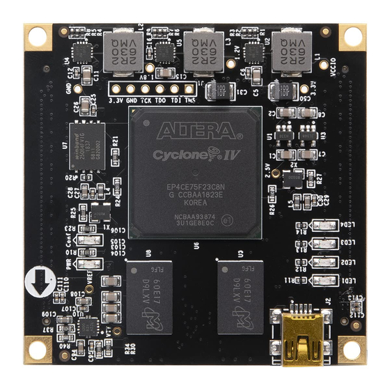
Figure 8-2: Power Indicator and Configure Indicator on the Core Board
The schematic diagram of the four user LED sections is shown below. In
Figure 8-3, When the FPGA pin output is logic 0, the LED will be lit.
Figure 8-3: User LED Schematic
Amazon Store: https://www.amazon.com/alinx
17 / 19
