- ページ 17
コンピュータ・ハードウェア Alinx ALTER AC4075のPDF ユーザーマニュアルをオンラインで閲覧またはダウンロードできます。Alinx ALTER AC4075 19 ページ。 Core board

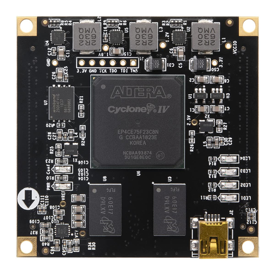
ALINX ALTERA Core Board AC4075 User Manual
Figure 8-1: Power Indicator and Configure Indicator schematic
Figure 8-2: Power Indicator and Configure Indicator on the Core Board
The schematic diagram of the four user LED sections is shown below. In
Figure 8-3, When the FPGA pin output is logic 0, the LED will be lit.
Figure 8-3: User LED Schematic
Amazon Store: https://www.amazon.com/alinx
17 / 19
