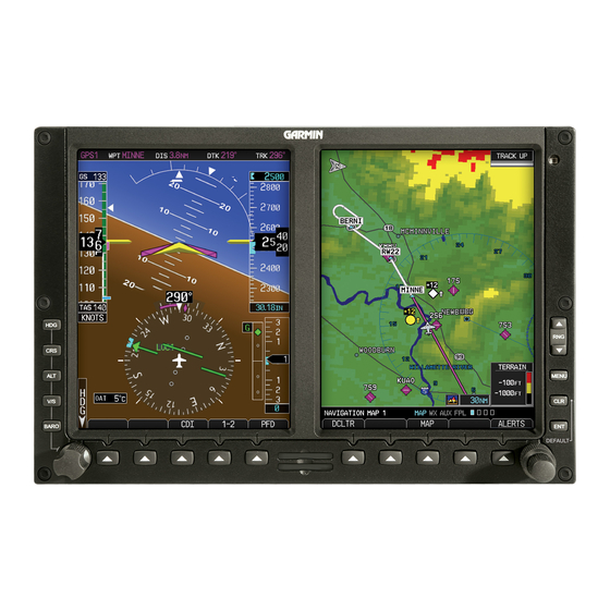
Garmin G500 Petunjuk Manual - Halaman 6
Jelajahi secara online atau unduh pdf Petunjuk Manual untuk Tampilan Avionik Garmin G500. Garmin G500 14 halaman. Primary flight and multifuction display system
Juga untuk Garmin G500: Referensi Cepat (2 halaman), Manual (40 halaman)

2.4 Servicing Information
None. In the event of system failure, troubleshoot the G500/G600 system in accordance with Section
2.6 Troubleshooting Information.
If the Mid-Continent Instruments 4300-4XX Electric Attitude Indicator or MD420 battery pack is installed,
the battery or batteries may be charged by one of the following methods:
1. Keep the battery or batteries plugged into the Attitude Indicator or Battery Module. Apply power
to the aircraft and run the unit overnight (approx. 15 hours) at the rated voltage.
2. Float Charging: Disconnect the battery or batteries from the indicator or module. Connect the
battery or batteries to a constant voltage source (battery plug (pin 1) red wire = positive) of 20.4
to 20.6 VDC continuously. Float charging may take 24 hours or longer to charge a battery pack.
3. Routine Charging: Disconnect the battery or batteries from the indicator or module. Connect the
battery or batteries to a constant voltage source (battery plug pin 1 red wire = positive) of 21.6 to
22.1 VDC with a current limit of 0.1 ampere maximum. When the charging current drops to
approximately 5mA, the battery is fully charged and should be disconnected. Leaving 21.6 to
22.1 VDC charge voltage on the battery for an extended time will degrade its life. If continuous
maintenance of the charge is desired, refer to step 2, Float Charging.
Battery out gassing and a rotten egg odor may occur due to
prolonged high rate overcharging and may result in battery
4. The Mid-Continent Instruments Battery Charger/Tester P/N 36029 may be used. This Battery
Charger/Tester will apply an initial charge, per step 3 above, and then automatically switch to
maintain a float charge, per step 2 above, indefinitely after initial charging is complete.
2.5 Periodic Maintenance Instructions
All G500/G600 system LRUs are designed to detect internal failures. A thorough self-test is executed
automatically upon application of power to the units, and built-in tests are continuously executed.
Detected errors are indicated on the GDU 620 display via failure annunciations.
Operation of the G500/G600 system is not permitted unless an inspection as described in this section
has been completed within the preceding 12 calendar months. Conduct a visual inspection (look for
signs of wear, deterioration, or damage to wires, switches, backshells, connectors, overbraid, bonding
straps or foil) of the G500/G600 system LRUs and wiring harnesses to ensure installation integrity:
1.
Inspect all units for security of attachment, including visual inspection of brackets and other
supporting structure attaching all units to the airframe.
2. Inspect all switches, knobs and buttons for legibility.
3. Visually inspect each unit's wiring for chafing or wear at each termination.
4. Visually check for any signs of corrosion.
2.5.1
Transient Voltage Suppressors (non-metallic aircraft only)
The GDU 620 #1, GRS 77 #1, GDC 74( ) #1, and GAD 43 (if installed) may have a TVS located at each
LRU. The electro-mechanical and electronic standby indicator (if installed) may have a TVS located at
the indicator and/or at the power bus. See G500/G600 AML STC Installation Manual Table K-2 to help
locate TVS installations. These components must be tested every 24 calendar months in accordance
with section 8.3.1 of the G500/G600 AML STC Installation Manual.
G500/G600 PFD/MFD System
Instructions for Continued Airworthiness
****WARNING****
damage. The battery assembly must be replaced if
out gassing has occurred.
190-00601-00 Rev. L
Page 6 of 14
