DFM CFB16 Panduan Operator - Halaman 14
Jelajahi secara online atau unduh pdf Panduan Operator untuk Aksesori Traktor DFM CFB16. DFM CFB16 20 halaman.

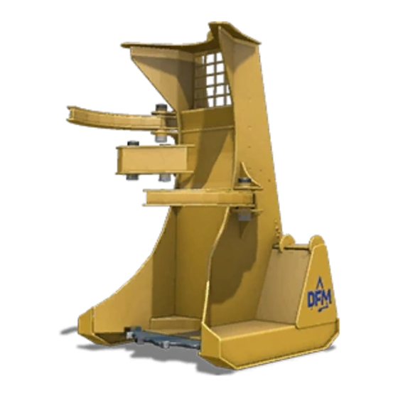
Attaching the Feller Buncher
Mounting the unit to the carrier consists of 3 steps;
failure to follow these steps may result in the unit
disengaging from the carrier, causing injury or death.
STEP 1: The Mounting Plate
The CFB16 is equipped with a universal mounting plate;
to attach the unit, drive the carrier toward the plate,
hook the plate with the carriers brackets, and roll the
carriers brackets backwards. After the operator has
successfully "hooked" the brackets onto the plate, the
operator then engages the brackets lock function. The
operator must then visually confirm the lock function has
been successfully engaged.
STEP 2: Connecting the Hydraulics
The next step is to connect the hydraulic hoses from
the unit to the carrier's auxiliary ports. CFB16 ships with
the correct hydraulic couplers for use on the carrier
specified. Standard flow units make use of 2 hoses to
operate,
igh flow models require a 3rd hose, acting as
h
a case drain to relieve excess back pressure. CASE
DRAIN LINE MUST BE ATTACHED AT ALL TIMES
WHEN IN USE, FAILURE TO DO SO WILL RESULT IN
DAMAGE TO THE HYDRAULIC SYSTEM, AND VOID
WARRANTY
The operator must line up the units couplers with the
correct couplers on the carrier side, and snap them into
place; the operator then rotates the couplers collar ¼
turn to engage the couplers lock function. Operator should
then visually confirm the couplers are all attached, and the
lock functions have been engaged.
STEP 3: Connecting the Electronics
The 3rd step is to hook up the electrical system. The CFB16
makes use of an electric over hydraulic circuit to engage
certain valves required to function properly, This
ship with one of two options. Option 1: for carriers with a
pin connection system the unit will ship with a pin connector,
and will utilize the carriers own joystick buttons to operate.
To hook up this option, the operator will plug the pin
connector into the carrier side socket. Option 2: for units
not equipped with pin connection system; the unit will ship
with a wiring harness; this wiring harness will contain 4
sealed buttons, connection plugs, and a length of electrical
wire; to hook up this option the operator will need to tap
into a 12 volt source, as well as attach the buttons in cab in a
convenient location. (See Diagram)
Wiring Diagram
Green ––––– Accumulator Arm - Open Function
Yellow ––––– Accumulator Arm - Close Function
Brown –––––––––– Grapple Arms - Open Function
Blue –––––––––– Grapple Arms - Close Function
Black ––––––––––––––––––––––––––––––Ground
Attaching the Feller Buncher | 8
u
nit will
