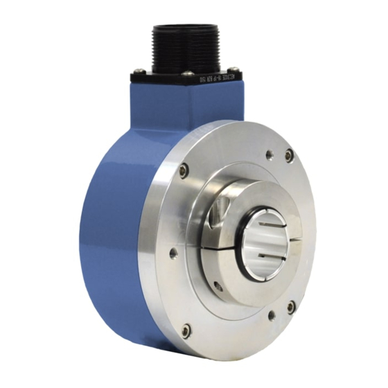
Avtron HS35A Petunjuk Manual - Halaman 3
Jelajahi secara online atau unduh pdf Petunjuk Manual untuk Konverter Media Avtron HS35A. Avtron HS35A 7 halaman. 1/2 inch to 1 inch [12mm-25mm] hollow shaft

The HS35A encoder can be wired for single phase or two-phase
operation, either with or without complements, with or without markers.
See connector options and wiring diagrams.
CAUTION
When wiring for differential applications (A,A,B,B,Z,Z), A
and A should be wired using one twisted, shielded pair;
B and B should be in a second pair, etc. Failure to use
complementary pairs (say, using A and B in a twisted
pair) will reduce noise immunity significantly.
For encoder output that correctly reflects the direction of rotation, proper
phasing of the two output channels is important. Phase A channel leads
phase B channel for clockwise shaft rotation as viewed from the back
(non-mounting side) of the encoder for standard phasing options ("A",
"C", "E", "G", "J", "M", "U", & "W"). Follow instructions under corrective
installation as needed to reverse the direction of output or purchase
HS35A with reverse (Dynapar HS35) phasing (options "B", "D", "F", "H",
"K", & "N").
CORRECTIVE ACTION FOR PHASE REVERSAL
If Encoder Direction is Reversed:
1)
Remove power.
2)
Exchange wires on cable, either at encoder cable end, or at
speed controller end (but not both):
a.) Single Ended 2 Phase Wiring (see wiring diagram below)
Exchange A and B at the user end of the wires.
b.) Differential 2 Phase Wiring (see wiring diagram below)
Exchange either A with A in the phase A pair OR B with B in
the phase B pair but NOT both.
ELECTRICAL
A. Operating Power (Vin)
1. Volts ..................................5-28V
2. Current ..............................50mA, no load
B. Output Format .......................A Quad B with marker (A,A
C. Signal Type ............................Incremental, Square Wave, 50% ±10%
.........................................Duty Cycle
D. Direction Sensing ..................Phasing with respect to rotation as
.........................................viewed from the back of the encoder
.........................................(non-clamping collar side).
Connector options "A", "C", "E", "G", "J", "M", "U", & "W": ØA
.........................................leads ØB for CW rotation
.........................................(Std. phasing).
Connector options "B", "D", "F", "H", "K", "N", & "T": ØA leads ØB
.........................................for CCW rotation
.........................................(Dynapar HS35 phasing).
E. Transition Separation ............15% minimum
F. Frequency Range ..................0 to 125kHz.
G. PPR ........................................100 - 5000 standard
H. Output....................................See Line Driver Options
MECHANICAL
A. Acceleration ..........................6,000 RPM/Sec.
B. Speed ....................................6,000 RPM max. (for higher RPM needs,
.........................................Consult Factory).
C. Shaft Diameter ......................0.500" to 1.000" [12mm to 20mm]
D. Shaft Engagement .......................1.250" to 2.250" [32mm-57mm] End-of-Shaft*
.........................................*1.750" to 2.250" with sizing inserts
.........................................Unlimited Thru Shaft
E. Weight ...................................1.6 lbs. (730g)
F. Starting Torque @ 25C ..........5oz in [0.035n-m] Max
3)
Apply power.
4)
Verify encoder feedback is correct, using hand rotation of
shaft, or jog mode of the speed controller.
Interconnecting cables specified in the wire selection chart are based on
typical applications. Refer to the "Wiring Diagrams" below for suggested
cable types. General electrical requirements are: stranded copper, 22
thru 16 gauge, each wire pair individually shielded with braid or foil with
drain wire
* Maximum cable length (and line driver selection) is limited by several
factors: line driver protection, maximum RPM, PPR, output voltage
and cable capacitance. The open collector driver (option 2) is much
more heavily limited by output frequency on long cable runs, and is
not recommended for new applications. These factors may dictate
maximum potential cable length.
SPECIFICATIONS
ENVIRONMENTAL
A. Enclosure Rating ...................NEMA 4, 13, IP65 (dust and water tight,
B. Operating Temp. ....................-20° to +100°C
–
–
–
,B,B
,Z,Z
)
C. Humidity ................................98% Non-condensing
D. Shock ....................................50G, 11 ms Duration
E. Vibration ................................5-2000Hz @ 20G
LINE DRIVER OPTIONS
Output Type
Line Driver
Voltage Input (Vin)
HS35A
3
.........................................not for immersion).
1
Differential Line
Driver
7272
5-28VDC
Reverse Voltage
Yes
Transient
Yes
Short Circuit
Yes
Output Options
2
4
Differential Line
Open Collector
Driver, 5V fixed
7273
7272
5-28VDC
5-28VDC
Yes
Yes
Yes
Yes
Yes
Yes
