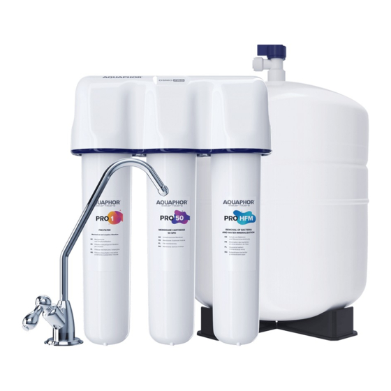
AQUAPHOR OSMO PRO 50 EU Manual - Halaman 6
Jelajahi secara online atau unduh pdf Manual untuk Sistem Penyaringan Air AQUAPHOR OSMO PRO 50 EU. AQUAPHOR OSMO PRO 50 EU 16 halaman.

Installation Guide
..........................................................................................
ATTENTION! Before installing OSMO Pro, it is
necessary to measure the pressure in the wa-
ter supply system and, if it exceeds 0.63 MPa
(6.5
), use a pressure regulator with the
bar
function of operating in a flow-free mode (the
pressure regulator is not included in the delivery
set, purchase separately).
ATTENTION! To connect OSMO Pro, it is re-
commended to contact the service department
of Aquaphor or regional dealers of Aquaphor.
..........................................................................................
Installing OSMO PRO*
1. For installation you will need: a drill, drill
bits 7 mm and 12 mm, an adjustable wrench,
a screwdriver, a tubular wrench 14 mm.
2. Determine convenient locations for the clean
water tap, operating unit, storage tank, instal-
lation site for the water supply connection
and drain clamp.
Fix the working unit so that the distance be-
tween the bottom point of the cartridges and the
floor is at least 5 cm. This is necessary for the
convenience of replacing the filter cartridges.
Make sure that the connecting pipes are loose
and not bent. Free pipe sections should be se-
cured so that they cannot be damaged or pulled
out of the connections by other objects.
OSMO Pro must be away from or isolated from
heat sources (dishwashers, washing machines,
stoves, boilers, hot water pipes, etc.).
Installation of a tap
for clean water
3. Shut off the cold water line and release the
pressure by opening the mixer.
4. Make sure there is a gasket in the union nut
(15) of the connection unit (23).
5. Drill a 12 mm hole in the sink (countertop).
6. Place the decorative stand (9), a large rubber
gasket (10) on the threaded shank (8) of the
tap and insert the tap into the hole of the sink.
* The manufacturer reserves the right to use components of
a similar design.
6
Water purifier installation diagr
1.
Housing
2. Water treatment unit
3. Reverse osmosis unit
4. Water conditioning unit
5. Outlet fitting
6. Connecting tube (blue)
with tapered sleeve
7.
Clean water tap
8. Threaded shank
9. Decorative stand
10. Rubber gasket, large
11. Small rubber gasket
12. Plastic lock washer
23
26
Position
"valve closed"
Cold water
supply
18
7. From the bottom of the tabletop, slide a small
rubber gasket (11), plastic (12) and metal (13) lock
washers onto the threaded shank and secure
the valve with a nut (14).
8. Slide the union nut (15) onto the clean water pipe
(6); insert the tube with the end with a metal bush-
ing into the threaded bushing of the valve and
screw the union nut until it stops. Check the tight-
ness of the tube for clean water – with a force of
8–10 kgf, the tube should not be pulled out.
Installing the drain clamp
It is recommended to install the clamp (17) on the
drain of the sink (sink) in front of the siphon (the
20
22
19
21
27
13. Me
14. Fix
15. Un
16. Dra
17. Dra
18. Sta
19. Sto
20. Sto
21. Co
22. A t
23. Co
24. Co
con
2
