Cisco 9124 - mds multilayer fabric switch Panduan Pemasangan Perangkat Keras - Halaman 6

Jelajahi secara online atau unduh pdf Panduan Pemasangan Perangkat Keras untuk Beralih Cisco 9124 - mds multilayer fabric switch. Cisco 9124 - mds multilayer fabric switch 36 halaman. Mds 9000 series
Juga untuk Cisco 9124 - mds multilayer fabric switch: Spesifikasi (2 halaman), Lembar data (9 halaman), Spesifikasi (3 halaman), Panduan Konfigurasi (49 halaman), Catatan Rilis (48 halaman), Catatan Rilis (44 halaman), Catatan Rilis (36 halaman), Catatan Rilis (22 halaman), Catatan Rilis (3 halaman), Catatan Rilis (40 halaman), Manual (16 halaman)
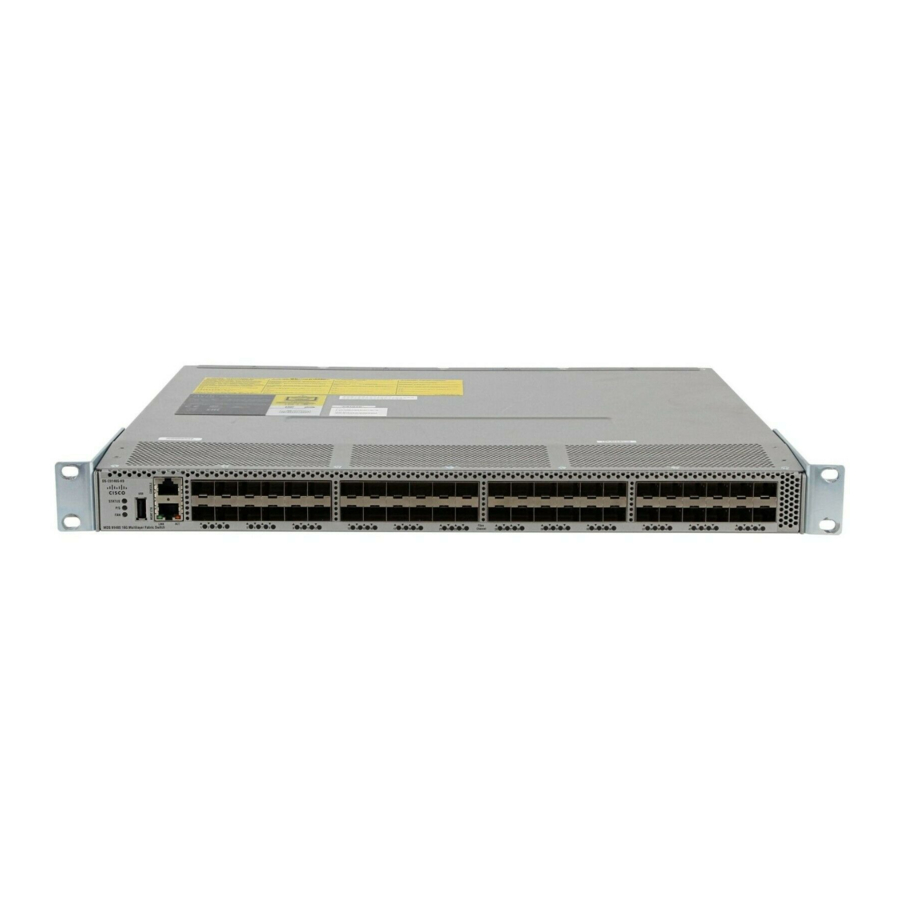
Cisco 9124 - mds multilayer fabric switch Panduan Pemasangan Perangkat Keras
Installing the Switch in a Cabinet or Rack
S e n d d o c u m e n t a t i o n c o m m e n t s t o m d s f e e d b a c k - d o c @ c i s c o . c o m
The rack-mount kit provided with the switch contains the items listed in
Table 2-1
Description
30- to 36-inch slider rails
24- to 30-inch slider rails
18- to 24-inch slider rails
Front rack-mount brackets
12-24 x 3/4-inch Phillips binder-head screws
10-32 x 3/4-inch Phillips binder-head screws
M4 x 6-mm Phillips flat-head screws
12-24 Cage nuts
Front-Facing Installation
To install the switch in a cabinet or rack using the rack-mount kit provided with the switch, follow these
steps:
Install the front rack-mount bracket as follows:
Step 1
a.
b.
Install the C brackets as follows:
Step 2
Note
a.
b.
Cisco MDS 9100 Series Hardware Installation Guide
2-6
Cisco MDS 9148, MDS 9134, and Cisco MDS 9124 Fabric Switch Rack-Mount Kit
Position one of the front rack-mount brackets against the side of the switch and align the screw holes
as shown in
Figure
2-1. Then attach the bracket to the switch with the three M4 screws originally
provided with the bracket.
Repeat with the other front rack-mount bracket on the other side of the switch.
Two C brackets are shipped preinstalled on the switch, using three M3 screws per bracket. This
installation step is only necessary if the C brackets were removed.
Position one of the C brackets against the side of the switch and align the screw holes as shown in
Figure
2-1. Then attach the bracket to the switch with the three M3 screws originally provided with
the bracket.
Repeat with the other C bracket on the other side of the switch.
Chapter 2
Installing the Cisco MDS 9100 Series
Table
Quantity
2 per kit
2 per kit
2 per kit
2 per kit
10 per kit
10 per kit
6 per kit
10 per kit
2-1.
OL-21514-01