Digitimer D400-2 Panduan Operator - Halaman 13
Jelajahi secara online atau unduh pdf Panduan Operator untuk Peralatan Perekaman Digitimer D400-2. Digitimer D400-2 20 halaman. Multi-channel 50/60hz mains noise eliminator, two/four channel

Digitimer Ltd – D400 Operator's Manual
Hardware Overview
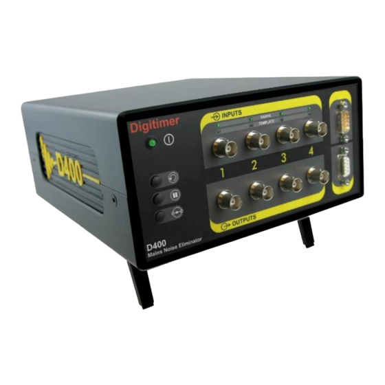
The D400 is designed for ease of use, has very few controls and is essentially "plug and
play". There are three push buttons on the left of the front panel and to the right of these
are multiple pairs of signal input and output connectors, as well as equivalent 9-way "D"
connectors for all channels. Associated with the individual signal connectors are several LED
indicators which show the status of each channel (see below).
D400 Front Panel Components
Power LED
Clear Button
Hold Button
Bypass Button
Power LED
Once powered on, the D400 will enter a start-up stabilisation phase signified by the front
panel POWER LED flashing green for approximately 40 seconds. This LED will be
permanently lit once the D400 is ready to use.
Signal Input/Output Connectors
The D400 offers the user two alternative methods for signal input and output connection.
For each channel there is a pair of standard BNC connectors designated "Inputs" and
"Outputs". In addition, two 9-way "D" connectors are available for combining input and/or
output signals via the supplied signal input/output cables.
The operational signal range of the D400 is ±10V and amplifiers or signal conditioners
providing voltages in excess of ±10V are not compatible with the D400.
Channel Status LEDs
BNC Signal Inputs/Outputs for Channel 1
13
Version 1.2
Combined
Signal Input
Connector
Combined
Signal Output
Connector
