Cisco UCS C480 M5 Manual - Halaman 3
Jelajahi secara online atau unduh pdf Manual untuk Server Cisco UCS C480 M5. Cisco UCS C480 M5 34 halaman.
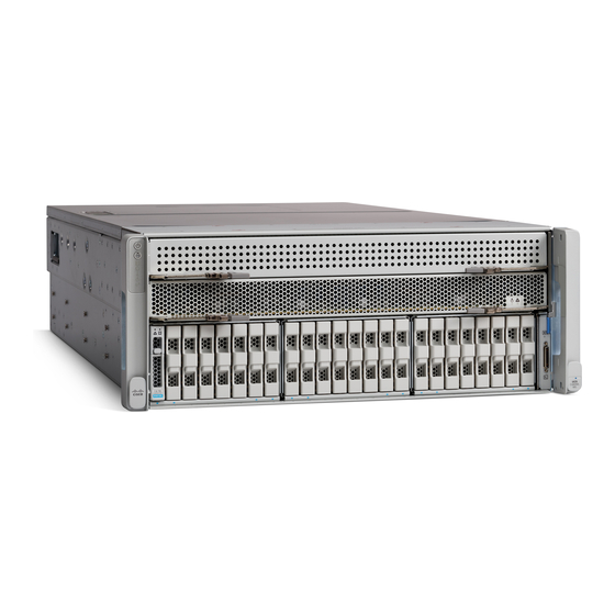
Server CPU Module Bay Layout
The front of the C480 M5 server is shown in
bay (Bay 1) and the upper bay (Bay 2).
The CPU numbering is as follows:
Lower Bay: CPU1 and CPU2
■
Upper Bay: CPU3 and CPU4
■
Figure 1
C480 CPU Module Bays
Each CPU has six memory channels, and each channel controls two memory DIMMs.
The channel numbering for each CPU is as follows:
Lower Bay:
CPU1: A, B, C, D, E, F
■
CPU2: G, H, J, K, L, M
■
Upper Bay:
CPU3: A, B, C, D, E, F
■
CPU4: G, H, J, K, L, M
■
Cisco UCS C480 M5 Memory Guide
Figure
1. Notice that there are two CPU Module bays, the lower
CPU Module Bay 2
CPU Module Bay 1
Server CPU Module Bay Layout
3