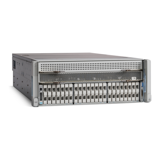
Server CPU Module Bay Layout
The front of the C480 M5 server is shown in
bay (Bay 1) and the upper bay (Bay 2).
The CPU numbering is as follows:
Lower Bay: CPU1 and CPU2
■
Upper Bay: CPU3 and CPU4
■
Figure 1
C480 CPU Module Bays
Each CPU has six memory channels, and each channel controls two memory DIMMs.
The channel numbering for each CPU is as follows:
Lower Bay:
CPU1: A, B, C, D, E, F
■
CPU2: G, H, J, K, L, M
■
Upper Bay:
CPU3: A, B, C, D, E, F
■
CPU4: G, H, J, K, L, M
■
Cisco UCS C480 M5 Memory Guide
Figure
1. Notice that there are two CPU Module bays, the lower
CPU Module Bay 2
CPU Module Bay 1
Server CPU Module Bay Layout
3
