CROW ELECTRONIC ENGINEERING NEO DT Petunjuk Instalasi
Jelajahi secara online atau unduh pdf Petunjuk Instalasi untuk Sensor Keamanan CROW ELECTRONIC ENGINEERING NEO DT. CROW ELECTRONIC ENGINEERING NEO DT 2 halaman. Passive infrared & microwave detector with end of line resistors
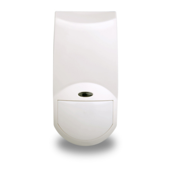
NEO DT
PASSIVE INFRARED & MICROWAVE DETECTOR With End Of Line Resistors
PRODUCT FEATURES
The NEO DT is a combination of PIR & MW detectors,
with PET immune function, providing protection from
intruders by PYRO sensor element and MW (based on
Doppler concept). Using micro controller for PIR & MW
signal analyzing, with special ASIC technology for PIR
pulse analyzing and unique optic for anti-mask
protection.
Quad (Four element) PYRO sensor.
Hard spherical lens for outstanding detection
performance and elimination of false alarms.
Microwave detection based on Doppler
concept.
Unique Microwave Motion Sensor Module.
ASIC VLSI based electronics with movement
speed spectrum analysis.
PIR self-test by applying a short heat pulse.
Height installation calibrations free.
User-friendly installation with or w/o swivel
bracket.
2-way Microwave sensitivity adjustment.
2-way PIR sensitivity adjustment.
Bi directional temperature compensation.
PET immunity up to 25Kg.
White light and environmental immunity.
SELECT MOUNTING LOCATION
Choose a location most likely to intercept an intruder.
(Our recommendation is a corner installation). See
detection pattern fig.5 or 6. The quad-element high
quality sensor detects motion crossing the beam; it is
slightly less sensitive detecting motion toward the
detector.
AVOID THE FOLLOWING LOCATIONS
Locations where there are large objects in a
range of 1m (3ft) from the detector.
Locations where there are air drafts or
substantial airflows.
Facing direct sunlight.
Facing areas that may change temperature
rapidly or large metal objects.
Do not install outdoors
Keep wiring away from electrical power
cables.
Do not install behind partitions.
The NEO DT performs better when provided with a
constant and stable environment.
WIRE SIZE REQUIREMENTS
Use #22 AWG (0.5 mm) or wires with a larger diameter.
Use the following table to determine required wire
gauge (diameter) and length of wire between the
detector and the control panel.
Wire Length
m
200
300
Wire Diameter
mm
.5
.75
Wire Length
ft.
656
984
Wire Gauge
AWG
22
20
Fig. 4 – Bracket installation options
DETECTOR INSTALLATION
The NEO DT can either be wall or corner mounted.
If ceiling or special wall mounting is required, use the
optional mounting bracket. Refer to bracket description.
(See fig. 4).
1. To remove the front cover, unscrew the holding screw
and gently raise the front cover.
2.
To remove the PC board, carefully
unscrew the holding screw located on the PC
board.
3. Break out the desired holes for proper installation.
A
A
B
B
A D
C
C
H
F
E
C
B
B
Fig. 2
The circular and rectangular indentations at the
base are the knock-out holes for wire entry. For
option with bracket - lead wire through the bracket
(see fig. 4)
4. Mount the detector base to the wall, corner or ceiling.
(For bracket option see fig.4).
5. Reinstall the PC board by fully tightening the holding
screw. Connect wire to terminal block.
6. Replace the cover by inserting it back in the
appropriate closing pins and screw in the holding
400
800
screw.
1.0
1.5
7. Detector breakage/removal monitoring (Back
1312
2624
Tamper). If the detector is forcibly removed from the
18
16
mounting surface, a TAMPER alarm is triggered. For
this, the detector base must be secured with an
additional screw. (This option is not valid in case of
bracket installation).
Fig. 5 - Wide Angle Lens Detection Pattern
Fig. 6 – Long Range Lens Detection Pattern
CONNECTING THE DETECTOR
The NEO DT might be installed with and without EOL
options.
The terminal block connector is build as follow:
TIN TOUT TEOL AIN AOUT SPR TEST + 12V -
Terminals 1&2 - Marked "+ 12V -" : Supply Voltage
Connect to the positive (Voltage supply) and negative
(Ground) of the alarm control unit.
Holding screw
Fig.1
Note: The supply connection to the Detectors must only
be to a Limited Power Source (LPS) for the input supply
in accordance with the Standard EN 60950-1 Latest
Revision.
Terminals 3 - Marked "TEST "
For wire access use
This pin is used to enable the LED for walktest when
holes A.
the LED Jumper is in AUTO mode.
For flat wall mounting
Apply 12VDC to this pin in order to enable the LED
use holes B.
activation during walktest.
For corner mounting -
use 4 holes C.
Terminal 4 – Marked "SPARE"
For 45° mounting - use 2
This pin is spare pin use to connect external EOL
holes C (left or right).
resistor.
For bracket mounting
Terminals 5 & 6 - Marked "ALARM IN & OUT "
use hole D for holding
These are the COMMON and the NC (Normally
screw.
Closed) outputs of ALARM relay.
For Detector breakage /
Connect to the zone input of the alarm control unit.
removal monitoring by
back tamper use hole E
Terminal 7 - Marked "TAMPER EOL"
in flat mounting or F in
corner mounting.
This pin is spare pin use to connect more then one
H hole is for the PC
detector on the same zone with the internal EOL
board holding screw.
resistor.
Terminals 8 & 9 - Marked "TAMPER IN & OUT"
Connect these terminals to a 24-hour normally closed
protective zone in the control unit. If the front cover of
the detector is opened, an immediate alarm signal will
be sent to the control unit.
Fig. 3 - End Of Line Resistor Options
Fig. 7 Long Range Curtain Lens Replacement
(4)
(1)
lens hooks to outside and push
Note: When using the Long Range detection option – Set
Switch 2 to ON.
INSTALLATION INSTRUCTIONS
TAMPER
ALARM
9
8
7
6
5
4
3
(2)
To fit lens press it into
To fit L/R mask remove
the cover from the front
the lens, place the mask in
until "CLICK" is heard
the center of lens housing
To remove lens, press both
(3)
Press the mask into
the cover from the front
the lens to the front.
until "CLICK" is heard
2
1