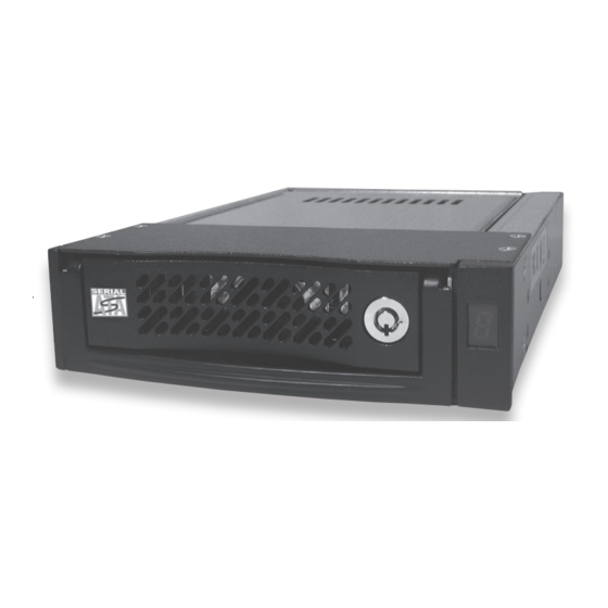
CRU Dataport Data Express DE110 Ultra ATA133 Manual
Jelajahi secara online atau unduh pdf Manual untuk Kandang CRU Dataport Data Express DE110 Ultra ATA133. CRU Dataport Data Express DE110 Ultra ATA133 2 halaman.

Data Express DE110 Ultra ATA133
Removable Ultra ATA133 Drive Enclosure
NOTES: For Ultra ATA133 (133MByte/sec) operation, an Ultra ATA133 controller
and hard drive (s), and appropriate 40-pin, 80-conductor cable are required.
Receiving Frame Motherboard
Master/Slave Selection Jumper (ID0 & ID1) - Master Drive
designation (jumper is factory-installed on ID0). Change jumper
position to Pins 3 & 4 (ID1) for Slave Drive designation.
Forces Master/Slave Drive configuration on the receiving frame, if
jumper option on the drive itself is configured for Cable Selection
(recommended configuration). Refer to section "Master/Slave Drive
Section" for further information.
If using the Drive Select Method, this option is instead used to
configure the unit ID display only (refer to section "Master/Slave
Drive Section" for further information).
Remote Activity LED (RLED) - These pins provide power for a re-
mote LED device activity indicator (Pin 13 = Cathode, Pin 14 = Anode).
Factory Reserved Pins - These pins are reserved for factory use
only - Do not install jumper under any circumstances!
DC Power
Connector (P1)
I/O Connector
Factory Reserved Pins
(JP1)
(no jumper installed)
Figure 1: Receiving Frame Motherboard (Rear View)
Master/Slave Drive Selection
There are two ways to set the Master/Slave Drive designation for the
DE110 unit, as described below.
1. Cable Select Method (Recommended Method): In most cases,
the drive will be factory configured as a Master Drive using a
jumper option on the drive itself. CRU-DataPort, recommends
reconfiguring the drive for Cable Select. This can be done by configuring
the jumper on the drive itself (refer to the drive manufacturer's
documentation for further information).
Option Pin
Master Drive
Connector (W1)
Select (ID0) (factory
installed jumper)
Slave Drive Select
(ID1)
= Pin 1
Rugged, Reliable, Mobile, Secure
When the drive is jumpered as double select, the Master/Slave
designation is handled by the Master/Slave Selection Jumper Option
(ID0 & ID1) located on the receiving frame motherboard. If neces-
sary, reconfigure jumper (jumper is factory-configured for Master
Drive designation). Skip "Drive Select Method" and continue with the
Installation process.
2. Drive Select Method: In most cases, the drive will be factory
configured as a Master Drive using a jumper option on the drive
itself. Reconfigure the jumper if necessary (refer to the drive
manufacturer's documentation for exact Master/Slave jumper
settings).
Reconfigure the jumper (jumper is factory installed on ID0 for Master
Drive designation) on the receiving frame motherboard to match the
hard drive.
NOTE: Since specifications (specifically, pin assignments)
between drive manufacturers may vary, please refer to your
drive manufacturer's documentation for exact information
regarding Master/Slave and Cable Select configuration.
Installation
1. Attach the DC power cable (from the drive carrier board) to the drive.
2. Carefully insert drive into the carrier. Slide the drive towards the
Drive Carrier Board, so that the I/O connector on the drive mates
with the connector on the Drive Carrier Board. Make sure that the
DC power cable is not pinched. Turn the drive/carrier assembly over.
3. Fasten the drive into place with four (4) #6-32 Phillips Flat Hd.
screws. Some drives may require minor adjustment before securing
into carrier with screws.
4. Install the provided drive cover.
1-800-260-9800
www.CRU-DataPort.com
TM
