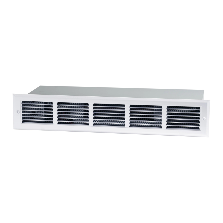
Dimplex RKHA Manual - Halaman 2
Jelajahi secara online atau unduh pdf Manual untuk Pemanas Listrik Dimplex RKHA. Dimplex RKHA 4 halaman. Under cabinet heater
Juga untuk Dimplex RKHA: Petunjuk Instalasi (2 halaman), Panduan Pemilik (3 halaman), Petunjuk Manual (10 halaman), Manual (4 halaman)

2. Cut 22 ⅜ in (568 mm) x 3 ⅝ in (92 mm) opening
(Figure 2). Keep clearance area free of obstructions.
3. Bring in service cable to left or rear of 10 in (254 mm)
minimum area as shown in Fig. 2.
4. Remove heater cover and appropriate knockout.
Attach service cable to unit with approved connector
and connect colour to colour in outlet box. To change
wattage or voltage connections, see Figure 5.
5. Replace cover, slide unit into opening, and secure
each side (Figure 1).
NOTE: Make sure unit is installed right side up.
!
Refer to "TOP" label.
For inspection of field wiring, see instruction under
"Electrical Inspection".
Soffit or Stair Riser Installation
1. Cut opening as for heater installation (22 ⅜ in
(568 mm) x 3 ⅝ in (92 mm)). Allow ¾ in (19 mm)
clearance below cabinet doors. Add supports for unit
(Figure 3).
2. Proceed as for heater installation. After securing unit
in opening, install combination of frame and grille
(Figure 1).
Operation
WARNING: This heater must be properly installed
before it is used.
1. Prior to energization remove all construction dirt
(plaster, sawdust, etc.) from interior and exterior of
heater.
2. Adjust thermostat with pliers. This unit is also
controllable from a line voltage wall thermostat or
field installed built-in tamperproof single or double
pole thermostat kit.
Dimplex Under Cabinet heaters are designed and tested
for safe and trouble-free operation and are protected
against overheating by a built-in thermal cutout. Free
airflow throughout the heater is extremely important for
the most efficient operation of the heater. Restricted
airflow may cause the thermal overload protector to
cycle the heater "ON and OFF". A cycling heater will not
supply sufficient heat to the room.
Avoid direct contact of paper, fabric, or furniture with
heater.
2
FIGURE 1
Heater Cover
Top Label
Junction Box Cover
Screw 'C'
Screw 'A'
FIGURE 2
10" MIN.
10" MIN.
Service
SERVICE
Cable
CABLE
22"
22"
KNOCKOUTS
Knockouts
FIGURE 3
CEILING
GRILLE
HEATER
CABINET
DOOR
FIGURE 4
CABINET
DOOR
HEATER
GRILLE
FLOOR
Heater
Element
Screw'B'
Grille
Optional Grille Frame
22-3/8"
22 3/8"
3 5/8"
3-5/8"
3-1/2"
3 1/2"
9-1/2"
9 1/2"
CLEARANCE 5" MIN.
3/4"
MIN.
PARTITION
OR ADDED
SUPPORT
PARTITION
OR ADDED
3/4
SUPPORT
MIN.
www.dimplex.com
