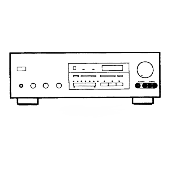
Yamaha DSP-A970 Panduan Pengoperasian - Halaman 21
Jelajahi secara online atau unduh pdf Panduan Pengoperasian untuk Penguat Yamaha DSP-A970. Yamaha DSP-A970 48 halaman. Digital sound field processing amplifier

5 Input Trim Control
Adjusts the input level of each source respectively.
6 Program Selector
Sequentially selects the digital sound field processing
programs in the + or – direction.
6 Display Panel
Shows program names, parameters and information about other
various settings and adjustments.
7 Effect Switch
Normally ON, this switch can be turned OFF to disable output
from the center and effect speakers.
8 Master Volume Control
Simultaneously controls signal level at all outputs: front effect,
main, rear effect, center, and subwoofer. (This does not affect
TAPE REC OUT level.)
9 Phones Jack
Plug in headphones here for private listening. If the FRONT
MIX and EFFECT switches are on, the effect channels will be
heard along with the main channels. Otherwise the main
channels only will be heard.
0 Bass and Treble Controls
Adjust the sound to match your tastes. Can also be used to
compensate for room acoustics. Defeated in the center
position.
A Balance Control
Adjusts the left and right output volume to the Main Speakers
to compensate for sound imbalance caused by speaker
positions or listening room conditions.
B Rec Out Switch
Used to select the source to be recorded to tape deck or VCR
independent of the selection of input source. When pressed,
the indicator corresponding to the currently selected source to
be recorded flashes. While an indicator is flashing, you can
change the selection of the source to be recorded with the
input selector switches. The selected source is also shown by
the display panel and the monitor screen (when the monitor is
on).
C Input Selector Switch
Sequentially selects the input source that you want to listen to
and/or watch in the
or
corresponding to the selected input source illuminates. The
selected input source is also shown by the display panel and
the monitor screen (When the monitor is on).
D Input Selector Switches for VCR 1, CD and LD
Directly selects VCR 1, CD or LD as the input source.
E Auxiliary Input Jacks (AUX 2)
Connect an auxiliary video or audio input source equipment
such as a camcorder to these jacks. If the connected video
equipment has a S video output terminal, connect it to the S
VIDEO jack to obtain a high resolution picture. The source
connected to these jacks can be selected by the input selector
switch.
direction. The indicator
19
