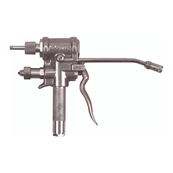
Alemite 7716-D1 Panduan Servis - Halaman 5
Jelajahi secara online atau unduh pdf Panduan Servis untuk Unit Kontrol Alemite 7716-D1. Alemite 7716-D1 12 halaman. High-pressure measuring control valve

High-Pressure Measuring Control Valve
Overhaul
NOTE : Refer to Figure 2 and/or Figure 3
for component identification on all overhaul
procedures.
Prior to performing any maintenance procedure, the
following safety precautions must be observed. Personal
injury may occur.
WARNING
Do not use halogenated hydrocarbon
solvents such as methylene chloride or 1,1,1-
trichlorethane in this valve. An explosion can
result when aluminum and/or zinc-plated parts
come in contact with halogenated hydrocarbon
solvents.
Release all pressure within the system prior to
performing any overhaul procedure.
• Disconnect the air supply line from the pump
motor.
• Into an appropriate container, operate the
control valve to discharge remaining pressure
within the system.
Never point a control valve at any portion of your
body or another person. Accidental discharge of
pressure and/or material can result in personal
injury.
Read each step of the instructions carefully. Make
sure a proper understanding is achieved before
proceeding.
Removal
Remove the control valve from its delivery line.
Disassembly
1. Clamp Valve Body ( 7 ) vertically in a soft-jaw vise with
the Inlet Handle facing upward.
2. Unscrew Extension ( 40 ) and Coupler ( 41 ) from the
Valve Body.
Inlet Handle
3. Unscrew Bushing ( 29 ) from Inlet Handle ( 28 ).
• Remove Gasket (30) from Bushing.
4. Unscrew Knurled Nut (34) from Stud (31).
Alemite Corporation
5. Remove Retaining Washer ( 33 ), Strainer ( 32 ), and the
Stud from the Bushing.
6. Unscrew the Inlet Handle from the Valve Body.
• Use a strap wrench or other suitable tool that will not
mar the surface of the Inlet Handle.
7. Remove O-Ring ( 27 ) from the Inlet Handle.
Valve Body
Lever and Valve Actuation Stem Travel Assembly
8. Remove Valve Guide ( 23 ) from the Valve Body.
• Use needle-nose pliers.
9. Remove Pin ( 38 ) from the Valve Body.
• Drive the Pin from the opposite of the knurled end
with a punch and hammer.
10. Remove Lever ( 24 ) from the Valve Body.
11. Remove Nut ( 36 ) and Setscrew ( 37 ) from the Lever as
required.
12. Unscrew Packing Screw (35) from the Valve Body.
13. Remove Valve Actuation Stem (39), Washer (14), and
Seal (13) from the Valve Body.
NOTE: The earlier units contain a leather
washer (not illustrated) that is no longer
required.
14. Unscrew Cap (18) from Retainer (15).
15. Remove Spring (17) and Washer (16) from the
Retainer.
16. Unscrew Nut (20) and Setscrew (19) from the Cap if
necessary.
17. Unscrew the Retainer from the Valve Body.
18. Remove the additional Washer (14), and Seal (13)
from the Valve Body.
Slide Valve and Seat Assembly
19. Remove the Slide Valve portion of Slide Valve and
Seat Assembly (22) from the Valve Body.
20. Remove Screws (26) and Lock Washers (25) that
secure the Seat to the Valve Body.
21. Remove the Seat and Gasket (21) from the Valve Body.
Adjusting Screw Assembly
22. Unscrew Plug (1) from the Valve Body.
• Remove O-Ring (2) from the Plug.
5
SER 7716-D1
Revision (11-95)
