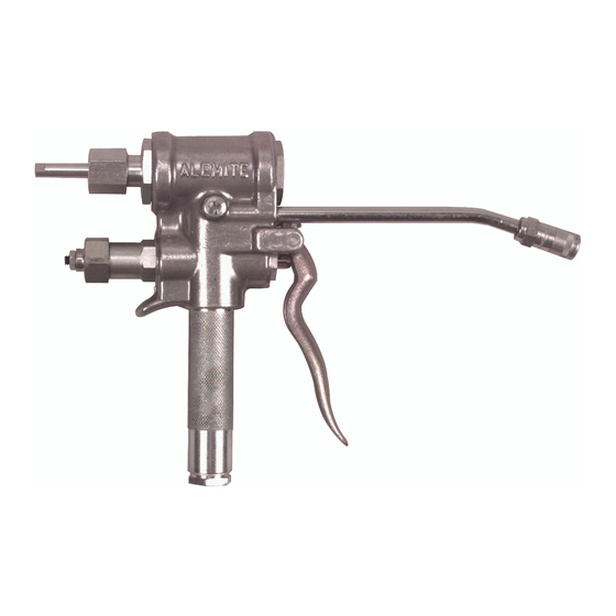
Alemite 7716-D1 Panduan Servis - Halaman 7
Jelajahi secara online atau unduh pdf Panduan Servis untuk Unit Kontrol Alemite 7716-D1. Alemite 7716-D1 12 halaman. High-pressure measuring control valve

High-Pressure Measuring Control Valve
Assembly
N OT E : P r i o r t o a s s e m b l y, c e r t a i n
components require lubrication in clean oil.
Refer to Table 4 for details.
Valve Body
Measuring Piston Assembly
1. Install Backup Ring ( 5 ) onto each end of Measuring
Piston ( 6 ).
• Seat each Ring against the center of the Piston.
2. Install V-Block Packing ( 4 ) onto each end of the
Measuring Piston.
• Make sure the lip of each Packing faces the outside
of the Piston.
3. Install O-Ring ( 3 ) onto each end of the Piston.
4. Clamp Valve Body ( 7 ) vertically in a soft-jaw vise with
the Inlet Handle port facing downward.
CAUTION
Use care installing the Piston assembly past the
threads of the Valve Body. Damage to the Packings
can occur.
5. Install the Piston assembly into the Valve Body.
Adjusting Screw Assembly
6. Install O-Ring (2) onto Plug (1).
• Make sure the O-ring does not roll.
7. Screw the Plug assembly into the discharge end of the
Valve Body.
8. From the opposite end of the Valve Body, seat the
Measuring Piston assembly against the Plug.
9. Install the additional O-Ring ( 2) onto Packing
Screw (8).
• Make sure the O-ring does not roll.
10. Grease the threads of Adjusting Screw (12).
11. Screw the Adjusting Screw fully into the Packing
Screw. This setting allows the maximum amount of
product to be dispensed.
Item No.
1n Figure 2
2
O-Ring, 1-5/16 " OD x 1-1/16 " ID
3
O-Ring, 15/16 " OD x 1-1/16 " ID
4
Packing, V-Block, 1.20 " OD
Alemite Corporation
Description
Table 4 Lubricated Components
7
12. Install V-Packing (9) [lip-end first] onto the stem of the
Adjusting Screw.
13. Screw Nut (10) onto the Packing Screw.
14. Screw the Packing Screw assembly into the Valve
Body.
• Tighten securely.
15. Tighten the Nut to the Packing Screw.
Slide Valve and Seat Assembly
16. Turn the Valve Body assembly end-for-end in the vise.
17. Install Gasket (21) into the Valve Body.
• Make sure the holes align properly.
18. Install Lock Washer (25) and Screw (26) into both
ends of the seat portion of the Slide Valve and Seat
assembly (22).
19. Install the Slide Seat and Screw assembly into the
Valve Body.
• Make sure the screw holes align properly. Tighten
both Screws securely.
20. Grease the face of the Valve portion of the Slide Valve
and Seat assembly (22).
21. Install the Slide Valve [cavity end first] onto the Seat.
• Make sure the Slide Valve and Seat are in proper
alignment.
Lever and Valve Actuation Stem Travel Assembly
CAUTION
Use care installing Seal (13) past the threads of the
Valve Body. Damage to the Seal can occur.
22. Install Seal (13) [lip end first] into each end of the
Valve Body.
• Make sure both Seals seat properly.
23. Install Washer (14) into each end of the Valve Body.
NOTE: The earlier units contain a leather
washer (not illustrated) that is no longer
required
Item No.
on Figure 2
9
V-Packing
13
Seal, 3/4 " OD x 3/8 " ID
27
O-Ring, 1.00 " OD x 13/16 " ID
SER 7716-D1
Description
Revision (11-95)
