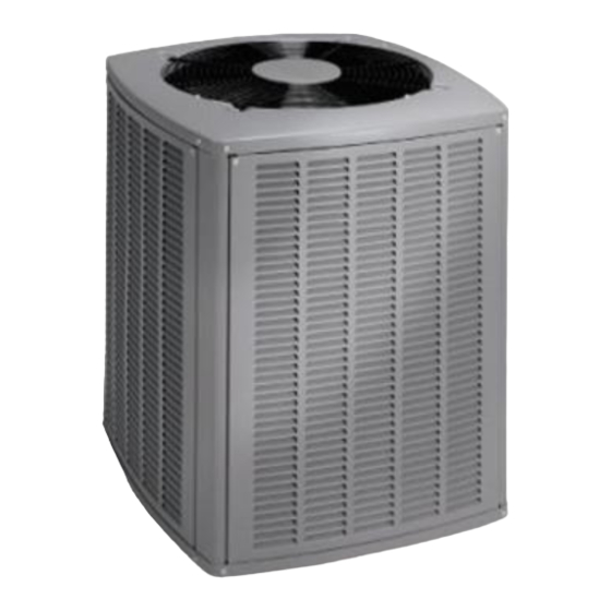
Armstrong Air Conditioning 4SCU13LE Series Panduan Petunjuk Pemasangan dan Pemeliharaan - Halaman 3
Jelajahi secara online atau unduh pdf Panduan Petunjuk Pemasangan dan Pemeliharaan untuk Pendingin Udara Armstrong Air Conditioning 4SCU13LE Series. Armstrong Air Conditioning 4SCU13LE Series 20 halaman. Split system air conditioner

Slab Mounting
Discharge Air
Building
Structure
2° or 2" per 5' slope tolerance away from building
structure.
Figure 2
Roof Mounting
Install unit at a minimum of 4" above surface of the roof.
Care must be taken to ensure weight of unit is properly
distributed over roof joists and rafters. Either redwood or
steel supports are recommended.
If unit coil cannot be mounted away from prevailing winter
winds, a wind barrier should be constructed (see Figure 3).
Size barrier at least the same height and width as the
outdoor unit. Mount barrier 24" from the sides of the unit in
the direction of the prevailing winds.
Wind Barrier Construction
Prevailing Winter Winds
Wind Barrier
Inlet Air
Inlet Air
Figure 3
Electrical Wiring
All field wiring must be done in accordance with the
National Electrical Code (NEC) recommendations,
Canadian Electrical Code (CEC) and CSA Standards, or
local codes, where applicable.
# 48387H005
Mounting Slab
Ground Level
24"
Inlet Air
WARNING
Unit must be grounded in accordance with
national and local codes. Failure to ground unit
properly can result in personal injury or death.
Refer to the furnace or blower coil Installation Instructions
for additional wiring application diagrams and refer to unit
rating plate for minimum circuit ampacity and maximum
overcurrent protection size.
1. Install line voltage power supply to unit from a properly
sized disconnect switch. Any excess high voltage field
wiring should be trimmed or secured away from the
low voltage field wiring.
2. Ground unit at unit disconnect switch or to an earth
ground. To facilitate conduit, a hole is in the bottom of
the control box. Connect conduit to the control box
using a proper conduit fitting. Units are approved for
use only with copper conductors. 24V Class II circuit
connections are made to the low voltage pigtails.
Refer to Figure 4 for field wiring diagram. A complete
unit wiring diagram is located inside the unit control
box cover (see also page 19 of this instruction).
Typical Field Wiring Diagram
NOTE: For use with copper conductors only. Refer
to unit rating plate for minimum circuit ampacity and
maximum overcurrent protection size.
WARNING – ELECTRIC SHOCK HAZARD
Can cause INJURY or DEATH. Unit must be grounded
in accordance with national and local codes.
Figure 4
3. Install room thermostat on an inside wall that is not
subject to drafts, direct sunshine, or other heat sources.
*
*
A4
TIMED OFF CONTROL
*
2
3
1
*
May be optional
208-230/60/1
(SEE NOTE)
GROUND
Page 3
