CAME Z Series Manual

Jelajahi secara online atau unduh pdf Manual untuk Panel Kontrol CAME Z Series. CAME Z Series 4 halaman. Control board
Juga untuk CAME Z Series: Manual (8 halaman), Manual (20 halaman), Manual (4 halaman), Manual (17 halaman), Manual (17 halaman), Manual (13 halaman), Manual (13 halaman), Manual (16 halaman), Manual (16 halaman), Manual (12 halaman), Manual (12 halaman), Manual (18 halaman), Panduan Instalasi (11 halaman), Manual (8 halaman), Manual (20 halaman), Manual (12 halaman), Manual (12 halaman), Panduan Dokumentasi Teknis (16 halaman), Petunjuk Manual (16 halaman), Petunjuk (4 halaman), Panduan Cepat (2 halaman), Manual Koneksi (4 halaman), Manual (4 halaman), Manual (12 halaman), Manual (20 halaman), Manual (15 halaman), Buku Petunjuk (12 halaman), Panduan Memulai Cepat (12 halaman), Manual (16 halaman)
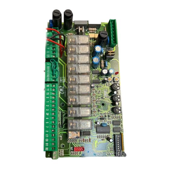
CAME Z Series Manual
CAME
STANDARDS
The K4 standard control set is for double leaf
swing gates using CAME 240Vac motors. All
components are designed by CAME SpA. to
the UNI8612 standard.
The ZA4 control board and transformer are
inside an insulated plastic enclosure (S4339)
secured closed with screws or a security seal
Contents
1 off S4339 enclosure
1 off ZA4 control board
1 off AF43s radio head
2 off TOP432s transmitter
1 off DIR10 photocell set
S4339
box
Supply
cable
W1
CABLE TYPES
The motor cable requires an earth, a neutral and
two live conductors with a current rating of 5A.
Duct cable should be waterproof. Final runs to
ATI motors must be flexible. FROG motors have
a 2 metre cable (excl. earth) fitted.
www.came.co.uk
Z
SERIES
STANDARD CONTROL SET
FOR DOUBLE LEAF GATES
CABLE PLAN
The plan shows the site from inside the property. A duct is shown across the
road containing a motor cable and a photocell cable. The junction box on
the right may be omitted for FERNI or FAST sets. Note the photocell cable
passes through the backs of the boxes and piers to photocell positions. The
mains supply should be armoured or in a duct. Always include a draw string.
Above ground cables have been shown unsleeved for clarity. Conduits are
tidy and good practice.
Photocell
cable
W5
Motor
cable
W2
Photocell cables should be 2 core and 4 core for
transmitter and receiver respectively. It is good
practice to use 4 core for both.
Helpline Tel: 0870 012 9000
SPECIFICATION
MOTOR.
Sequenced operation of two motor outputs with adjustable torque.
SEQUENCE CONTROL.
Adjustable motor run time, adjustable timed re-closure, and
adjustable leaf delay. Timed re-closure is switch enabled.
RADIO CONTROL
12 bit coded transmitters. Plug-on receiver head with 433MHz
SAW filter. Flash memory single code storage.
SAFETY
Single photocell safety circuit to re-open during closure in fault
condition. Normally closed circuit. Fail safe photocell logic.
POWER
240Vac supply internally fused at 5A.
24Vac accessory output not to exceed 20W loading.
Photocell
Cable
W6
Photocell
height
500mm
Motor
cable
W4
QP-K4
K4
Motor
cable
W3
Technical
Document
Rev 1.0
2/2005
Junction
box
- 1 -