Camille Bauer SINEAX CAM Panduan Petunjuk Pengoperasian - Halaman 3
Jelajahi secara online atau unduh pdf Panduan Petunjuk Pengoperasian untuk Alat Ukur Camille Bauer SINEAX CAM. Camille Bauer SINEAX CAM 19 halaman. Graphic display for sineax cam
Juga untuk Camille Bauer SINEAX CAM: Panduan Petunjuk Pengoperasian (12 halaman)

Overview
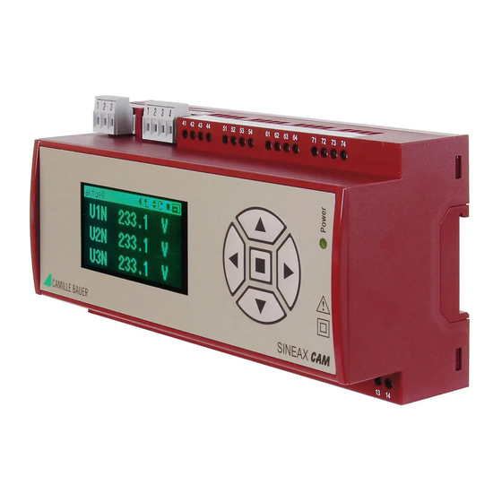
The optional graphic display is intended for on-site visualization of measurement data, lists and
alarms of the SINEAX CAM. The operation of the display is performed by means of the keys.
Using the keys the user may acknowledge alarms or extreme values as well. Which data can be
displayed depends on the version of the device, especially which I/O modules are present and
which options are activated. Also the configuration of the measurement unit influences the data
display. The most influencing factor in this context is the connected system.
The parametrization of the graphic display and the assembly of user specific measurement
displays are done using the CB-Manager Software. But settings like contrast or display language
may also be performed by means of the operating keys.
Content
1. Display structure and operation .............................................................................................. 4
2. Settings...................................................................................................................................... 5
2.1 Settings of the display ........................................................................................................... 5
2.2 Settings of the interface......................................................................................................... 5
2.3 Settings of the clock .............................................................................................................. 6
3. Security system ........................................................................................................................ 7
4. Display measurements ............................................................................................................. 8
4.1 Customer specific measurement displays ............................................................................. 8
4.2 Measurement display of system quantities............................................................................ 9
4.3 Measurement display of harmonics ..................................................................................... 10
4.4 Display meter contents ........................................................................................................ 11
4.5 Measurements of I/O's and relays ....................................................................................... 11
4.6 Measurement display of mean values ................................................................................. 12
4.7 Measurements for wiring control.......................................................................................... 13
5. Alarms...................................................................................................................................... 14
6. Lists.......................................................................................................................................... 15
7. Logger...................................................................................................................................... 18
8. Menu overview ........................................................................................................................ 19
3
