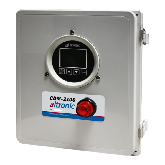
Altronic CDM-2100 Panduan Pengoperasian - Halaman 11
Jelajahi secara online atau unduh pdf Panduan Pengoperasian untuk Alat Ukur Altronic CDM-2100. Altronic CDM-2100 20 halaman. Differential pressure monitor

9.8 RX, TX INDICATORS:
RX and TX (receive and transmit) LEDs on the back of the gauge indicate when
the unit is receiving or transmitting data.
9.9 CONNECTING TO A PC:
When connecting the gauge to the RS-232 port on a PC, an RS-232 to RS-485
converter must be used for the communication interface.
9.10 LOADING:
RS-485 uses a balanced differential pair of wires switching from 0 to 5 volts to
communicate data. In situations where many units (32 max.) are connected
together on a long run, voltage drop on the communications leads becomes a
major problem. Voltage drops on the RS-485 minus lead appear as a common
mode voltage to the receivers. While the receivers are rated to a maximum
voltage difference of ±7 volts, -7 V to +12 V, a practical system should not have a
voltage difference exceeding ±3 volts under normal conditions. The wire gauge
used for the connections, therefore, limits the maximum number of units or
the maximum length of wire between units in each application. The following
formula can be used as a guideline to select the appropriate wire gauge.
For 18 AWG wire
For 20 AWG wire
For 22 AWG wire
10.0 MODBUS REGISTER LISTS
The maximum number of registers that can be read at one time is limited to 32.
The maximum number of booleans that can be read at one time is limited to 256.
All communications are at 9600 baud (default), see section 9.3 for other speeds
8 Data bits, No Parity, 1 Stop bit (9600 8N1).
10.1 00000 SERIES REGISTERS
ADDRESS
DESCRIPTION OF FUNCTION
00001
PROTECT CONFIGURATION
Protect configuration from being changed by keypad
00002
PROTECT SETPOINT
Protect setpoints from being changed by keypad
00003
PROTECT COMMUNICATIONS
Protect against ModBus writes
00004
PROTECT CALIBRATION
Protect against changing calibration values
00005
DISPLAY LOOP
Display loop value on home screen
00006
RESET MIN/MAx
Reset MIN/MAx readings
00008
RESERVED
00016
00017
SWITCH 1 RESET
00018
SWITCH 1 STATE
00019
SWITCH 1 TYPE
00020
RESERVED
00024
00025
SWITCH 2 RESET
00026
SWITCH 2 STATE
00027
SWITCH 2 TYPE
CDM-2100 OM 3-21
All rights reserved © ALTRONIC, LLC 2021
No. of units = (4000)/(ft. of wire used)
No. of units = (2500)/(ft. of wire used)
No. of units = (1600)/(ft. of wire used)
0=OFF 1=ON
0=OFF 1=ON
0=OFF 1=ON
0=OFF 1=ON
0=OFF
0=SHELF
0=NON-LATCH
0=SHELF
0=NON-LATCH
NOTE: The maximum number of units
connected in a system is 32.
NOTE: All temperatures are stated
in 0.1 DEG. Kelvin (for universal
compatibility). Therefore a register
value of 2730 is 273.0° K, which is 0°
C, or 32° F.
1=ON
1=RESET
1=RESET
1=FAILSAFE
1=LATCHING
1=RESET
1=FAILSAFE
1=LATCHING
11
