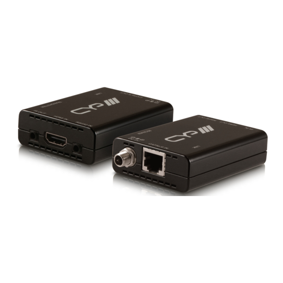
CYP PU-513L-KIT Panduan Pengoperasian - Halaman 8
Jelajahi secara online atau unduh pdf Panduan Pengoperasian untuk Pemanjang CYP PU-513L-KIT. CYP PU-513L-KIT 16 halaman.

6. OPERATION CONTROLS AND FUNCTIONS
6.1 Transmitter Front and Rear Panels
IR OUT
HDMI IN
1
2
1
IR OUT
Connect to the supplied IR blaster for IR signal transmission to the source
equipment. Place the IR blaster in direct line-of-sight of the equipment
to be controlled.
2
HDMI IN
Connect to the HDMI input source devices such as a DVD player or a Set-
top Box with HDMI cable or DVI to HDMI cable.
3
RS 232 IN
Connect the 3.5mm mini-jack to D-Sub 9-pin female adaptor cable
(included in the package) to a PC or control system with D-Sub 9-pin
cable for the transmission of RS-232 commands.
4
DC 5V
Plug the 5V DC power supply into the unit and connect the adaptor to
an AC outlet.
5
CAT5e/6/7 OUT
Connect to the receiver unit with a single CAT5e/6 /7cable for
transmission of all data signals. The yellow LED will illuminate when
both the transmitter and receiver are connected and are powered. The
green LED will illuminate when the device is connected to the power
supply.
8
RS232 IN
3
DC 5V
CAT5e/6 OUT
4
5
